background image

16 • 1/16 SUMMIT VXL

The electronic speed control is factory set and should not require any 
adjustments.  These instructions are provided for your reference.

Setup Programming

 (Calibrating your ESC and transmitter)

Read through all of the following programming steps before you begin. 
If you get lost during programming or receive unexpected results, 
simply unplug the battery, wait a few seconds, plug the battery back in, 
and start over.  

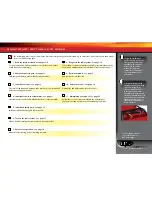
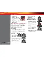
1. Disconnect each of the motor wires between the ESC and the motor. 

This is a precaution to prevent runaway when the speed control is 
turned on before it is programmed.

2. Connect a fully charged battery pack to the ESC. 

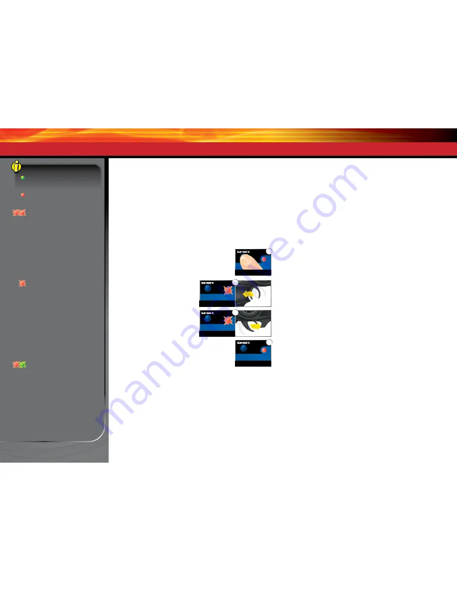
3. Turn on the transmitter (with the throttle  

at neutral).

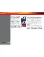
4. Press and hold the EZ-Set button (A).  

The LED will first turn green and then red.  
Release the EZ-Set button. 

5. When the LED blinks RED ONCE, 

pull the throttle trigger to the  
full throttle position and hold it 
there (B).

6. When the LED blinks RED TWICE, 

push the throttle trigger to the full 
reverse and hold it there (C).

7. When the LED starts flashing GREEN, programming 

is complete. After the throttle is returned to 
neutral, the LED will then shine solid green or red 
(depending on the Low-Voltage Detection setting) 
indicating the VXL-3m is on and at neutral (D).

ESC Operation
Note:

 In steps 1-7 below, Low-Voltage Detection is turned off (factory 

default) and the LED shines RED. If Low-Voltage Detection is on, the LED 
will shine GREEN instead of RED in steps 1-7 below. 
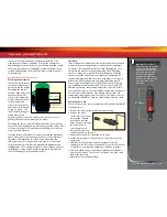
To operate the speed control and test the programming, place the 
vehicle on a stable block or stand so all of the drive wheels are off the 
ground. Reconnect the motor wires. Always make sure that objects and 
fingers are clear of the wheels.

1. With the transmitter on, press the EZ-Set button for ½ second, until 

the LED shines GREEN, then immediately release the button. This 
turns on the ESC. If you press and release too quickly, you may hear 
the steering servos jump, but the LED may not stay on. 

2. Apply forward throttle. The LED will turn off until full throttle power is 

reached. At full throttle, the led will shine RED.

3. Move the trigger forward to apply the brakes. Note that braking 

control is fully proportional. The LED will turn off until full braking 
power is reached. At full brakes, the LED will shine RED.

4. Return the throttle trigger to neutral. The LED will shine RED.

5. Move the throttle trigger forward again to engage reverse (Profile #1). 

The LED will turn off. Once full reverse power is reached, the LED will 
shine RED. 

6. To stop, return the throttle trigger to neutral. 

7. To turn the ESC off, press the EZ-Set button until the RED LED   

turns off. 

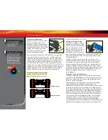
VXL-3m Thermal Shutdown Protection

The VXL-3m is also equipped with thermal shutdown protection. If the 
operating temperature exceeds safe limits, the ESC will reduce power 
to 50% and the LED will flash red. Additional heating will cause the 
speed control to shut down completely until it reaches a safe operating 
temperature. Traxxas encourages you to stop driving as soon as the 
thermal overload protection is activated.

ESC Profile Selection

The speed control is factory set to Profile #1. To change the profile, 
follow the steps described on the next page. The speed control should 
be connected to the receiver and battery, and the transmitter should be 
adjusted as described previously. The profiles are selected by entering 
the programming mode.

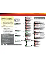
ADJUSTING THE ELECTRONIC SPEED CONTROL

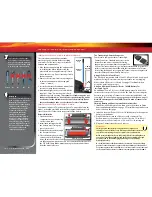
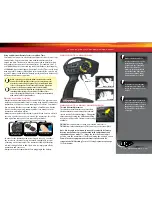
A

Green then Red

D

Solid

Once Red

B

Twice Red

C

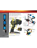
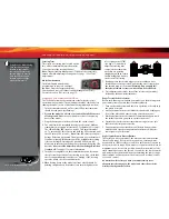
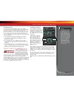
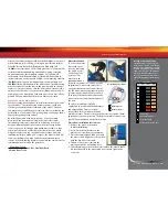
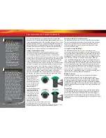
VXL-3m LED codes

Solid Green

: VXL-3m power on  

light. Low-Voltage Detection is  
ON (LiPo setting).

Solid Red

: VXL-3m power on light.  

Low-Voltage Detection is OFF  
(NiCad/NiMH setting).

Fast Blinking Red

: Thermal Shutdown 

Protection Stage 1. If the motor has 
lower than normal power and the VXL-3m 
is hot, the VXL-3m has entered Stage 1 
Thermal Shutdown Protection to guard 
against overheating caused by excessive 
current flow. If the motor has no power 
and the VXL-3m is very hot, the VXL-3m 
has entered Stage 2 Thermal Shutdown 
Protection and has automatically shut 
down. Let the VXL-3m cool. Make sure 
your model is properly geared for the 
conditions (

see page 23). 

Slow Blinking Red

 (with Low-Voltage 

Detection on)

:  The VXL-3m has entered 

Low-Voltage Protection.  When the 
battery voltage begins to reach the 
minimum recommended discharge 
voltage threshold for LiPo battery packs, 
the VXL-3m will limit the power output 
to 50% throttle. When the battery 
voltage attempts to fall below the 
minimum threshold, the VXL-3m will 
shut down all motor output. The LED on 
the speed control will slowly blink red, 
indicating a low-voltage shutdown. The 
VXL-3m will stay in this mode until a fully 
charged battery is connected. 

Alternating; Blinks Red then Green

:  If 

the motor has no power, the VXL-3m 
has entered Over Voltage Protection. 
If a battery with too high voltage  is 
used, the VXL-3m will go into a fail-safe 
mode. 

Warning

: If input voltage exceeds 

approximately 20 volts, the ESC may be 
damaged. Maximum peak input voltage 
limits are 12.6V in LiPo Mode (

see page 

17

) and 18V in NiMH Mode.

Содержание 72076-3

Страница 1: ...owner s manual MODEL 72076 3...

Страница 2: ...support options are Quick Start This manual is designed with a Quick Start path that outlines the necessary procedures to get your model up and running in the shortest time possible If you are an expe...

Страница 3: ...public roads or congested areas where its operation can conflict with or disrupt pedestrian or vehicular traffic Never under any circumstances operate the model in crowds of people Your model is very...

Страница 4: ...e risks associated with LiPo battery use Traxxas does not recommend that anyone under the age of 14 use or handle LiPo battery packs without the supervision of a knowledgeable and responsible adult Yo...

Страница 5: ...ent APPLYING THE DECALS The main decals for your model have been applied at the factory Additional decals are printed on self adhesive clear mylar and are die cut for easy removal Use a hobby knife to...

Страница 6: ...Shock Traxxas High Current Connector Chassis Front Body Mount Rear Body Mount Push Rod Hex Hub Pivot Ball Axle Carrier Rocker Front Bumper Transmission Spring Pre load Adjuster Slipper Clutch LED Ligh...

Страница 7: ...11 11 Maintaining your model See page 25 The transmitter requires 4 AA alkaline batteries sold separately Follow these critical steps to maintain the performance of your model and keep it in excellen...

Страница 8: ...ngs coils on the perimeter of the motor can and the magnets are mounted to the spinning rotor shaft Cogging Cogging is a condition sometimes associated with brushless motors Typically it is a slight s...

Страница 9: ...djusting the steering trim knob on the face of the transmitter Thermal Shutdown Protection Temperature sensing electronics used in the electronic speed control detect overloading and overheating of th...

Страница 10: ...3 CH2 Speed Control CH1 Steering Servo CH1 Channel 1 Not used Accessory sensor ports for use with standard voltage temperature and RPM telemetry sensors see Traxxas com and included materials for more...

Страница 11: ...arger with you wherever you want to have radio controlled fun Do not charge batteries inside of an automobile Read the Safety Precautions section of this manual 1 Plug the charger into a 12 volt autom...

Страница 12: ...Traxxas High Current Connector Your model is equipped with the Traxxas High Current Connector Standard connectors restrict current flow and are not capable of delivering the power needed to maximize t...

Страница 13: ...of the radio signal can cause you to lose control of your model In order for the transmitter and receiver to bind to one another the receiver in the model must be turned on within 20 seconds of turni...

Страница 14: ...left or right turn off TSM see page 15 and slowly adjust the steering trim control on the transmitter until they are pointing straight ahead then return the Multi Function knob to the desired TSM set...

Страница 15: ...ble as TSM makes corrections for you without intruding on your fun or creating unexpected side effects The Multi Function knob on the TQi transmitter has been programmed to control TSM The recommended...

Страница 16: ...eutral The LED will shine RED 5 Move the throttle trigger forward again to engage reverse Profile 1 The LED will turn off Once full reverse power is reached the LED will shine RED 6 To stop return the...

Страница 17: ...D on the speed control will slowly blink red indicating a low voltage shutdown The VXL 3m will stay in this mode until a fully charged battery is connected The electronic speed control is factory set...

Страница 18: ...es of batteries that are available and the methods with which they can be charged it s impossible to give exact run times for the model Another major factor that affects run time is how the model is d...

Страница 19: ...ot submerge the motor under water Do not gear the motor by temperature when running in wet conditions The motor will be cooled by water contact and will not give an accurate indication of appropriate...

Страница 20: ...er and remove the receiver Receiver Installation 1 Route the antenna wire out of the receiver box cover A Place the cover on the chassis 2 Route the servo and speed control leads into the receiver box...

Страница 21: ...ping effect Changing the oil to a higher viscosity oil will increase damping Lowering the viscosity of the oil will cause the suspension damping to be reduced Damping should be increased with higher v...

Страница 22: ...ission gears It may also be used to regulate the amount of power sent to the rear wheels to prevent tire spin When it slips the slipper clutch makes a high pitch whining noise To adjust the slipper cl...

Страница 23: ...model which will reduce performance and may overheat the motor and speed control Use the following formula to calculate the overall ratio for combinations not listed on the gear chart Motor Installati...

Страница 24: ...eometry of the model The offsets and dimensions designed into the model s wheels are intentional therefore Traxxas cannot recommend the use of other non Traxxas wheels with different specifications Ex...

Страница 25: ...ocks full Use only 100 pure silicone shock oil to prolong the life of the seals If you are experiencing leakage around the top of the shock inspect the bladder in the top cap for signs of damage or di...

Страница 26: ...rvo travel applied to steering Turning the Multi Function knob fully clockwise will deliver maximum steering throw turning the knob counter clockwise reduces steering throw note turning the dial count...

Страница 27: ...remember the Steering Percentage setting Adjustments you make to Steering Sensitivity will be applied to the 50 steering throw setting you selected previously Likewise setting the Multi Function knob...

Страница 28: ...m a list of model memory entries The transmitter and receiver do it all for you automatically To activate Model Lock 1 Switch on the transmitter and receiver you wish to lock 2 Press and hold MENU Rel...

Страница 29: ...the TQi transmitter s various settings and functions Press and hold MENU to enter the Menu Tree and use the following commands to navigate through the menu and select options MENU When you enter a men...

Страница 30: ...ED blinks x3 Press MENU twice red LED blinks x3 Turn steering wheel to desired max left and right travel x8 Press SET to save each position Turn steering wheel to test settings IF END POINTS ARE OK Pr...

Страница 31: ...averages Use the recording function to document your dashboard view with sound so that you can keep your eyes on your driving and not miss a single apex Manage up to 30 Models with Traxxas Link The T...

Страница 32: ...6250 TRAXXAS WAY MCKINNEY TEXAS 75070 1 888 TRAXXAS 151116 72076 3 OM N EN R01 owner s manual MODEL 72074 3...

Отзывы: