background image

27

CPSMC18xx-xxx PointSystem

Chassis

chassis

4.1.3

Grounding Lugs

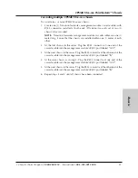
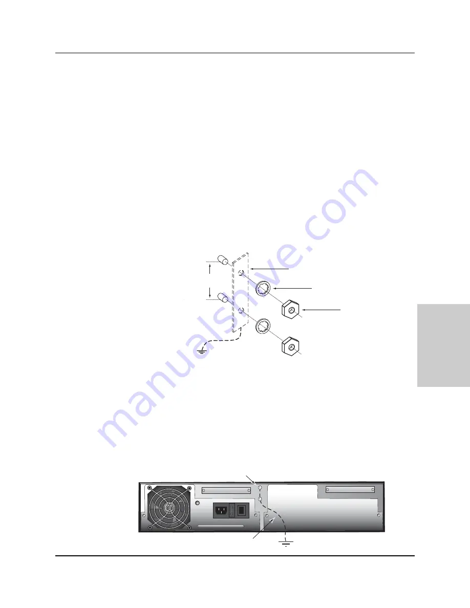
The CPSMC18xx-xxx comes equipped with grounding lugs, which are provided for
a grounding conductor wire terminated with a 

two-hole, compression-type,

grounding connector

.  The grounding wire -- which must be a copper conductor --

is not included with the chassis and must be provided by the customer/installer.   

The electrical conducting path from the chassis must:

Flow via the grounding lugs to the Common Bonding Network (CBN) for
telecom installations; or to an alternate approved grounding system (if required)
for non-telecom installations,  

Be of sufficiently low impedance to conduct fault currents likely to be imposed
on the chassis, and 

Enable proper operation of any over-current protection devices.  

The two-hole, compression-type, grounding connector 

must be fastened to the

grounding lugs with the enclosed, anti-rotation star-washers and lug-nut fasteners

.

The required torque to the fasteners is specified by the connector’s manufacturer.  

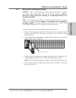
To properly ground the CPSMC18xx-xxx chassis:

1. Obtain one (1) properly-terminated, grounding conductor (12 AWG copper

wire gauge or larger) with a two-hole, compression-type, grounding connector.
Note the manufacturer's applied torque that is required for the connector.  

2. Attach the grounding conductor to the chassis by placing the two-hole,

compression-type connector onto the grounding lugs and fasten with
appropriate lock-washers and lug-nuts at the proper torque.

3. Attach the opposite end of the properly-terminated grounding conductor to the

Common Bonding Network (CBN) for telecom installations, or to an approved
grounding system (if required) for non-telecom installations.

24-hour Technical Support:

1-800-260-1312

-- International: 

00-1-952-941-7600

I
0

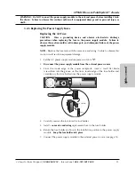
Grounding Lugs

CBN (for telecom installation)
or Earth Ground

Grounding Wire with a two-hole, 

compression-type grounding connector

3/4-inch

spacing

Grounding lugs

(6-32, 1/8" diam.)

Two-hole, compression-type

grounding connector (not included)

Star washer (included)

Lug nuts (included)

12 AWG copper wire

(not included)

Содержание PointSystem CPSMC1800-200

Страница 1: ...Transition Networks CPSMC18xx xxx 18 Slot PointSystem Chassis User s Guide revision C CPSMC1800 200 CPSMC1810 200 CPSMC1850 150 CPSMC1850 160...

Страница 2: ...f the Canadian Department of Communications Le pr sent appareil num rique n met pas de bruits radio lectriques d passant les limites applicables aux appareils num riques de la Class A B prescrites dan...

Страница 3: ...wering the CPSMC18xx xxx 14 3 1 AC Power Supply Module 14 3 2 DC Power Supply Module 16 3 3 Optional Dual Power Supply Modules 18 3 4 Power Supply Module Maintenance 19 3 4 1 Primary Secondary Managem...

Страница 4: ...assis 5 Network Management 34 5 1 Hardware Connections 34 6 Troubleshooting 36 Technical Specifications 37 Cable Specifications 38 Contact Us 40 Warranty 41 24 hour Technical Support 1 800 260 1312 In...

Страница 5: ...tion such as Transition Networks FocalPoint management software installed at a remote Network Management Station NMS A remote Web browser A command line interface CLI at an attached terminal A command...

Страница 6: ...e CPSMC18xx xxx also comes equipped with a pair of grounding terminals grounding lugs for providing proper grounding of the chassis Finally the CPSMC1850 150 and CPSMC1850 160 models include two 2 50...

Страница 7: ...18xx xxx 18 Slot PointSystem chassis Item Part Number Redundant AC Power Supply Module CPSMP 200 optional Redundant 48 VDC Power Supply Module CPSMP 210 optional Redundant Fan Module CPSFM 200 optiona...

Страница 8: ...nstall a chassis face plate over any unused chassis slot by aligning the hole in the face plate with the threaded hole in the chassis Secure the face place with the enclosed bolt 2 1 2 Calculating the...

Страница 9: ...the module 3 Carefully slide the slide in module into the installation slot while aligning the module s circuit board with the installation guides NOTE Ensure that the slide in module is firmly seate...

Страница 10: ...crew is at the top 3 Carefully slide the replacement slide in module into the installation slot while aligning the module s circuit board with the installation guides NOTE Ensure that the slide in mod...

Страница 11: ...ngle Slot Master Management Module CPSMM 200 Dual Slot Master Management Module The optional CPSMM 200 Dual Slot Master Management Module can also be installed in the CPSMC18xx xxx chassis to enable n...

Страница 12: ...lots at the far left position of the chassis 1b CPSMM 120 Single Slot Master Management Module OR CPSMM 210 Single Slot Expansion Management Module If chassis face plates are covering the installation...

Страница 13: ...module in the CPSMC18xx xxx chassis 1 Remove the management module to be replaced by loosening the panel fastener screw that secures the module to the chassis front Slide the module from the chassis 2...

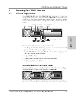
Страница 14: ...n AC power connector on the power supply module An On Off switch that when set to I allows the module to supply power to the chassis and any installed modules A power LED indicator A fan to prevent th...

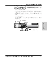
Страница 15: ...ough the AC power supply module 1 Set the On Off switch to 0 2 Connect female end of the power cord to the AC power connector on the power supply module 3 Plug the male end of the power cord into the...

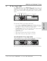
Страница 16: ...nd a negative connector on the DC power supply module An On Off switch that when set to I allows the DC power supply module to supply power to the chassis and any installed modules A power LED indicat...

Страница 17: ...wiring for the presence of earth ground A readily accessible disconnect device as part of the building installation shall be incorporated into the fixed wiring The disconnect device a 48 VDC 15 or 20A...

Страница 18: ...talled in the same chassis NOTE The drawing below shows the AC module in the left installation slot and the DC module in the right However either power supply module can be installed in either install...

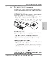
Страница 19: ...or as the Secondary power supply module As the Primary power supply it provides power to the entire chassis As the Secondary power supply it waits in stand by ready to supply power to the chassis in...

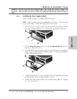
Страница 20: ...rotective plate from the installation slot by removing and retaining the two 2 screws that secure the plate to the chassis 2 Set the Primary Secondary switch and the Management Manual switch if necess...

Страница 21: ...y module power switch to 0 2 Disconnect the power supply module from the external power source 3 Remove the two 2 screws that secure power supply module to the chassis Retain the screws for installing...

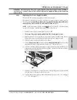
Страница 22: ...ting Failure to observe this caution could result in equipment damage 1 Set the AC power supply module power switch to 0 2 Disconnect the power supply module from the external power source 3 From the...

Страница 23: ...ent damage 1 Set the DC power supply module power switch to 0 2 Disconnect the power supply module from the external power source 3 Remove the power supply module by removing the two 2 screws that sec...

Страница 24: ...module NOTE The fan module may be hot swapped To install the fan module into the CPSMC18xx xxx chassis 1 Remove the protective plate from the installation slot by removing and retaining the two 2 scr...

Страница 25: ...g power supply modules If the CPSMC18xx xxx chassis is installed in a closed or multi unit rack assembly the operating ambient temperature of the the rack environment may be greater than room ambient...

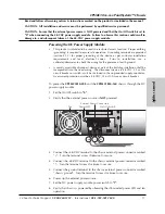
Страница 26: ...through the universal bracket installation holes 4 Using a Phillips screwdriver install the three 3 screws through the mounting bracket into the installation holes on side of the chassis 5 Repeat ste...

Страница 27: ...d torque to the fasteners is specified by the connector s manufacturer To properly ground the CPSMC18xx xxx chassis 1 Obtain one 1 properly terminated grounding conductor 12 AWG copper wire gauge or l...

Страница 28: ...nals from Telco connector 2 go to slots 7 12 Signals from Telco connector 1 go to slots 13 18 24 hour Technical Support 1 800 260 1312 International 00 1 952 941 7600 I 0 Telco connector 2 Telco conne...

Страница 29: ...o fiber optic cable For more information on the CDFTFxxxx 10x see the user s guide on line at www transition com Please note that Slots 1 6 on the CPSMC1850 1xx are designed for any Transition Network...

Страница 30: ...Port 2 CDFTF100 Fiber Port 1 Fiber Port 2 upper ports lower ports Conversion Center PS Power In Use 1 Power In Use 2 CPSMC1800 CPSMC1800 ESD Gnd Term UPPER LOWER UPPER LOWER UPPER LOWER UPPER LOWER UP...

Страница 31: ...stand by mode If the primary module fails the stand by module automatically takes over and manages the network Pwr RESET Pwr RESET 10BASE T IN RX TX LNK PWR OUT RESET DB 9 The CPSMM 200 Management Mo...

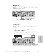
Страница 32: ...d within one 1 meter of each other 2 At the first chassis in the series Plug the RJ 45 connector at one end of the cascade cable into the management module s RJ 45 port labeled OUT 3 At the next chass...

Страница 33: ...F110 CFMFF100 CFMFF100 LKS PWR LKM LKS PWR LKM Multimode Singlemode TX RX TX RX LKF PWR RXF RXC LKC LA PWR RXF RXC LNK COL SPD PWR FRX CRX FLNK CLNK SPD PWR FRX CRX FLNK CLNK RX TX 10 100TX RX TX 10 1...

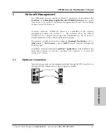
Страница 34: ...configure and manage the CPSMC18xx xxx chassis from an attached terminal or from a remote networked computer The firmware includes the Transition Networks Command Line Interface CLI a telnet server a...

Страница 35: ...RXC LNK COL SPD PWR FRX CRX FLNK CLNK SPD PWR FRX CRX FLNK CLNK RX TX 10 100TX RX TX 10 100SX 100BASE TX RX TX 100BASE FX Link Alert E D 0 50 Multimode Singlemode TX RX TX RX LA PWR RXF RXC LNK COL L...

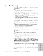
Страница 36: ...ot Press the RESET button on the management module Contact Technical Support U S Canada 1 800 260 1312 International 00 1 952 941 7600 3 For the remaining slide in modules are ANY of the power LEDs NO...

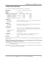
Страница 37: ...12 5 Amp maximum Environment Tmra 0 to 50 C 32 to 122 F Manufacturer s rated ambient temperature 0 to 60 C 32 to 140 F when redundant power or fan module is used Storage Temperature 40 to 80 C 40 to 1...

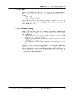
Страница 38: ...ata Set Ready DSR 6 Request To Send RTS 7 Clear To Send CTS 8 The table below shows the pin assignments for the RS 232 null modem cable RJ 45 Cable Category 5 Gauge 24 to 22 AWG Attenuation 22 0 dB 10...

Страница 39: ...equirements of the media and port type For example Shielded RJ 45 cable used for 100Base Tx Ethernet MUST be grounded at both cable endpoints via shielded RJ 45 jacks Shielded RS 232 cable MUST have t...

Страница 40: ...transition com Address Transition Networks 6475 City West Parkway Minneapolis MN 55344 USA telephone 952 941 7600 toll free 800 526 9267 fax 952 941 2322 Declaration of Conformity Name of Mfg Transit...

Страница 41: ...defective product for warranty coverage contact Transition Networks technical support department for a return authorization number Transition s technical support department can be reached through any...

Страница 42: ...by Transition Networks for a fee will carry a 180 day limited warranty All warranty claims are subject to the restrictions and conventions set forth by this document Transition Networks reserves the...

Отзывы: