CPSMP-210 48VDC and CPSMP-220 24VDC Power Supplies
8
24-Hour Technical Support: 1-800-260-1312 -- International: 00-1-952-941-7600
Installation—continued
Power source circuit requirements
The CPSMP 210 and 220 power supplies must be connected to a Safety Extra Low
Voltage (SELV) circuit. The installer must first determine circuit characteristics; for
example, limited current, and hazardous energy levels, etc., and then install the power
supply in accordance with local and national electrical codes.
Equipment ground
WARNING: The power supply has a provision for grounding. Equipment
grounding is vital to ensure safe operation. The installer must ensure that the power
supply is properly grounded during and after installation. Failure to observe this
warning could result in an electric shock.
Disconnect requirements
WARNING: A readily accessible, suitable National Electrical Code (NEC) or
local electrical code approved disconnect device and branch-circuit protector must
be part of the building's installed wiring to accommodate permanently connected
equipment. Failure to observe this warning could result in an electric shock, even
death.
WARNING: Ensure that the disconnect device for the external power source is
OPEN
(turned OFF)
before disconnecting or connecting the power leads to the
power supply. Failure to observe this warning could result in an electric shock,
even death.
CAUTION: While installing or servicing the power supply, wear a grounding
device and observe all electrostatic discharge precautions. Failure to observe this
caution could result in damage to, or failure of the power supply.
Connecting external power
To connect the external power to the power supply:
1. Slide the power ON/OFF switch to the OFF position.
2. Make sure that the external power source is turned OFF
(disconnect device open).
3. First, onnect the power source ground lead to chassis ground. See Figure 8.
4. Connect the positive DC lead to the terminal block “+.”
5. Connect the negative DC lead to the terminal block “-.”
!
!
!
!
+
-
External Power Cables
Power Supply Terminal Block
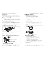
Figure 8: Power Supply Terminal Block and External Power Cable Connections
[email protected] -- Click the “Transition Now” link for live Web chat.
9
Connecting external power—continued
6. Power UP the external power source
(disconnect device is closed).
7. Slide the power ON/OFF switch to the ON position.
8. Verify that the power supply module is functional by noting that the fan is ON and
the power LED is lit. If not, see Troubleshooting on page 13.
Redundant
(failover)
chassis power supply
Note:
In a dual redundant power supply configuration, the fan will operate while the
power supply’s ON/OFF switch is in the OFF position. This provides extra
chassis heat exhaust when the supply is not in use in stand-by mode.
I
MPORTANT
:
•
In a multiple power supply chassis, one power supply configuration switch must
be set to master . If both modules are set to slave neither will supply sufficient
power to the chassis.
•
Power supply load sharing
(configuring multiple supplies as masters in a chassis)
is not recommended
(no load balancing capability)
.
To install and set up a second power supply for redundancy
(failover)
:
1. Slide the power supply’s power switch to the OFF position.
2. Make sure that the external power source is turned OFF.
3 Remove and keep the two (2) 6-32 philips head screws holding the power-supply
slot cover. See Figure 9.
4. Set up the second power supply’s configuration switch. See page 5.
5. Slide the second power supply in to the chassis as shown in Figure 10.
6. Secure the power supply to the chassis with the two (2) 6-32 philips head screws.
Power-Supply Slot Cover
6-32 Philips
6-32 Philips
Figure 9: Chassis Power-Supply Slot Cover
Figure 10: Power Supply Installation
CPSMP-210 48VDC and CPSMP-220 24VDC Power Supplies


