12
BAS-SVU24G-EN
Balancing Tool Dialog Boxes
Use the dialog boxes described in this section to perform the main balancing tasks on individual
VAV boxes, blower coils, fan coils, unit ventilators, and water source heat pumps. To perform
balancing tasks on multiple devices, see
.
N
No
otte
e:: For coverage of the main Balancing Tool screens, see the Tracer TU Balancing Tool Getting
Started Guide (TTU-SVN07). For procedural information and screen help, see the Tracer
TU Balancing Tool Help, which is integrated in and accessible within the software
application.
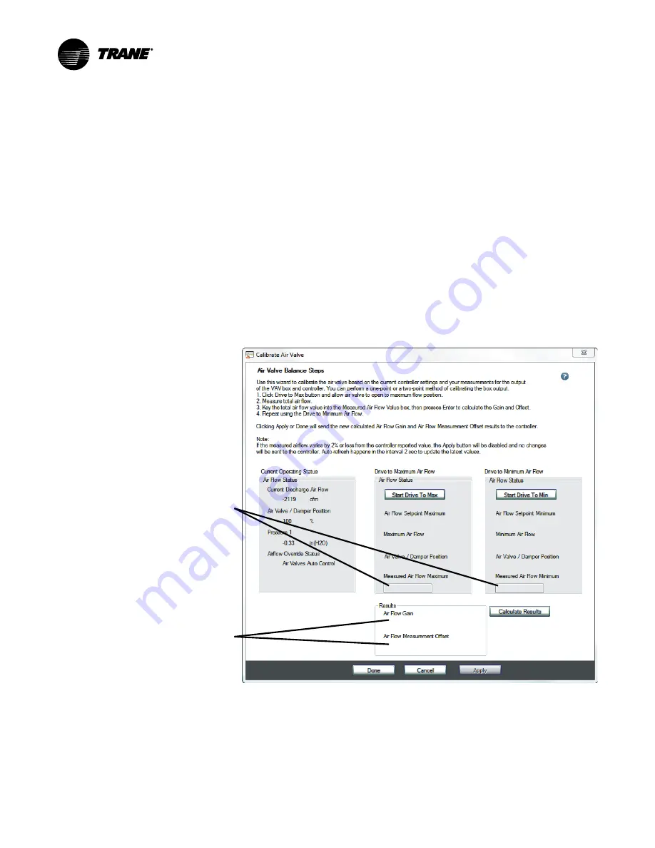
The Calibrate Air Valve Dialog Box
The Calibrate Air Valve dialog box appears when you click the Calibrate Air Valve S
Stta
arrtt button on
the Flow Calibration screen. You can use this dialog box to perform a two-point air valve
calibration.
N
No
otte
e:: Tracer TU presents the Hot Deck Air Valve Balancing Steps dialog box when a dual duct
VAV box is being calibrated. (See
“The Hot Deck Air Valve Balancing Steps Dialog Box,” p.
and “Hot Deck Air Valve Balancing Steps” (dialog box help) in the Tracer TU Balancing
Tool Help.)
Figure 7. The Calibrate Air Valve Dialog Box
Enter Measured Air
Flow Maximum and
Minimum values here.
Resulting Air Flow Gain
and Air Flow Measure-
ment Offset values are
displayed here after
you enter the Measured
Air Low Maximum value
and then again after you
enter the Measured Air
Flow Minimum value.
Current Operating Status Box
Initially displays the following values as of the time the dialog box is opened:
•
Current Discharge Air Flow
•
Air Valve / Damper Position
•
Pressure 1
•
Air Flow Override Status
Содержание Tracer TU
Страница 19: ...BAS SVU24G EN 19 N No ot te es s...


