Installation
16
CLCH-SVX08C-EN
Duct Connections
All duct connections to the gas heat section should be
installed in accordance with the standards of the National
Fire Protection Association (NFPA) and the Sheet Metal
and Air Conditioning Contractors National Association,
Inc. (SMACNA).
Combustion Air Duct
•
Outdoor units with internal vestibules have a rain hood
that requires field mounting.
•
Outdoor units with external vestibules do not have a
rain hood. Combustion air enters through openings in
the bottom of the vestibule.
•
All indoor units ship with a screened opening on the
combustion air inlet.
If combustion air is to be ducted to the gas heat vestibule,
the unit’s capacity must be derated to account for the
resistance in the air duct. For every 0.14 inches wg of duct
resistance, unit capacity (MBh output) will reduce by five
percent.
If combustion air is ducted to the vestibule air intake, the
perforated inlet panel on the side of the vestibule needs to
be cut out before ducting to the unit.
If combustion air is ducted to the vestibule, it is strongly
recommended that an experienced gas heat technician
check the system and emission levels in the exhaust flue at
start up. Carbon dioxide should be between 8.2 and 9.4
percent. This corresponds to the allowable range of excess
air needed for combustion. The additional static pressure
of the inlet air duct may change the fuel-air ratio slightly
necessitating system adjustment.
Separated combustion can be a desirable option, but will
require more field-installation time and material. The
burner fans are not sized to handle any static in the
combustion air stream. A booster fan will likely be
required to overcome combustion air duct static.
Combustion air cannot be ducted directly to the
combustion air fan. The airflow through the vestibule is
needed to keep the temperatures in the vestibule down.
Duct Transitions
When the gas heat section is the last section of the air
handler, and duct transitions should be smooth and
uniform from all sides. Follow recommendations for duct
transitions from SMACNA.
Fasten the ductwork directly to the ductwork opening.
When using lined ductwork, the insulation should not
obstruct the discharge opening.
Airflow Direction
The airflow direction through the gas heater is important
because it prevents localized “hot spots” on the heat
exchanger. Airflow direction labels denoting correct
airflow direction through the gas heat section are provided
on the burner side of the heating section. See
Airflow from the supply fan should enter on the drum (or
primary) side of the heat exchanger (
) and exit on
the tube (or secondary) side (
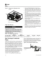
Figure 10. Airflow direction label
Figure 11.
Entering airside (drum or primary) of gas
heat section
Note: Reference burner nameplate for recommended gas manifold pressure at startup.
Содержание K01K12345
Страница 21: ...Wiring CLCH SVX08C EN 21 Figure 16 Natural gas 200 320 MBh 10 1 turndown...
Страница 22: ...Wiring 22 CLCH SVX08C EN Figure 17 Natural gas 360 1000 MBh 3 1 and 10 1 turndown and propane 200 1000 MBh...
Страница 23: ...Wiring CLCH SVX08C EN 23 Figure 18 Single phase natural gas and propane 1250 2000 MBh 3 1 and 10 1 turndown...
Страница 25: ...Wiring CLCH SVX08C EN 25 Figure 20 Natural gas and propane1250 2400 MBh 20 1 turndown...
Страница 34: ......
Страница 35: ......

