RT-SVX056D-GB
26
Grounding
Be sure to ground the unit and differential protection
should be suited for industrial machinery with current
leak which can be higher than 300 mA (several motors
and frequency drives).
CAUTION!
To avoid corrosion, overheating or general damage,
at terminal connections of power supply wiring, unit
is designed for copper mono-conductors only. In case
of multiconductor cable, an intermediate connection
box must be added. For cable with alternative material,
bi-material connecting devices are mandatory. Cable
routing inside control panel should be made case by
case by installer.
WARNING Ground Wire!
All field-installed wiring must be completed by qualified
personnel. All field-installed wiring must comply with
local codes and regulations. Failure to follow this
instruction could result in death or serious injury.
All power supply wiring must be sized and selected
accordingly by the project engineer in accordance with
local codes and regulations.
WARNING!
The Warning Label which is displayed on the equipment
and shown on wiring diagrams and schematics. Strict
adherence to these warnings must be observed. Failure
to do so may result in personal injury or death.
CAUTION!
Units must not be linked to the neutral wiring of the
installation. Units are compatible with the following
neutral operating conditions:
TNS
IT
TNC
TT
Standard**
Special
Special
Standard*
* Differential protection should be suited for industrial
machinery with current leak which can be higher than
300 mA (several motors and frequency drives).
Neutral wire not distributed.
** Neutral wire not distributed
Electrical Connections
The electric panel is located on the length of the indoor
section behind the plug fan section. The unit is designed
to run with 400V (+/-10%) - 50 Hz (+/-1%) - 3 ph.
2 glands are available on each unit to be able to connect
the unit to the main supply either from the side or from
the bottom.
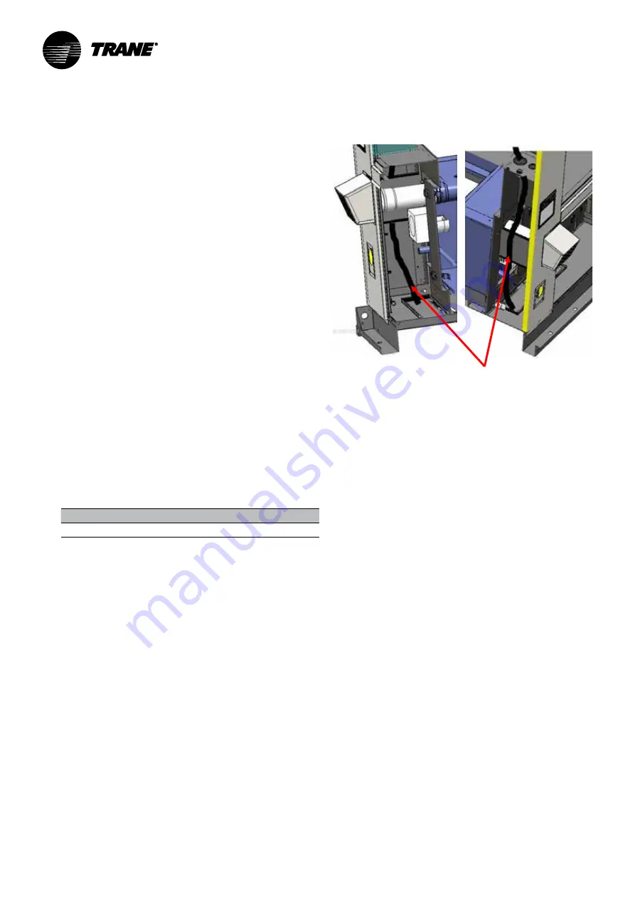
CAUTION!
Be sure that layout of electrical conduit is remote
enough from hot components (burner, electrical
heater...).
Figure 14 - Supply Power wiring layout to avoid hot areas
Example of wiring layout of supply power
to avoid hot area
CAUTION!
After completion of wiring, check all electrical
connections, and ensure all connections are tight.
Replace and secure all electrical box covers and access
doors before leaving unit or connecting power to circuit
supplying unit.
Scroll compressors
Proper phasing of the electrical power wiring is
critical for proper operation and reliability of the scroll
compressor and fans.
Proper rotation of the scroll compressor must
be established before the unit is started. This is
accomplished by confirming that the electrical phase
sequence of the power supply is correct. The motor is
internally connected for clockwise rotation with the inlet
power supply phased A, B, C.
The direction of rotation may be reversed by
interchanging any two of the line wires. It is this
possible interchange of wiring that makes a phase
sequence indicator necessary if the operator is to
quickly determine the phase rotation of the compressor
motor.
The “ABC” indicator on the face of the phase indicator
will glow if phase is ABC for terminals L1, L2, and L3.
Oil Injection Valve: This is specific for Scroll compressor
with variable frequency drive (VFD).
Compressor drive:
In case of replacement, configuration will be done by
Trane service. There is no human interface and the
configuration is done via RS485 Modbus.
Drive cabinet is cooled by a fan on the bottom behind
the door. Air entering from the bottom through a grid
with filter and leaving from the top through a grid with
filter.
Filter maintenance: clean or change the drive filters if
necessary.
Installation


