2
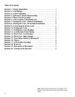
Table of Contents
Section 1. Safety Information
. ......................................................................... 3
Section 2. Unit Design
. ........................................................................................ 4
Section 3. Unit Preparation
. ............................................................................. 6
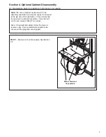
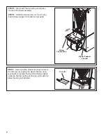
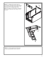
Section 4. Optional Cabinet Disassembly
. ............................................... 7
Section 5. Place Unit at Location
. ............................................................... 12
Section 6. Unit Location Considerations
. ............................................... 13
Section 7. Setting the Unit - Vertical Installation
. ................................ 18
Section 8. Setting the Unit - Horizontal Installation
. ......................... 20
Section 9. Connecting the Duct work
. ...................................................... 21
Section 10. Refrigerant Line
. ......................................................................... 22
Section 11. Refrigerant Line Brazing
. ....................................................... 23
Section 12. Condensate Drain Piping
. ...................................................... 26
Section 13. Electrical - Low Voltage
. .......................................................... 28
Section 14. Electrical - High Voltage
. ......................................................... 33
Section 15. Time Delay Switch Adjustment
. .......................................... 35
Section 16. Filters
. ............................................................................................... 35
Section 17. Unit Outline Drawing
. ............................................................... 36
Section 18. Start Up
. ........................................................................................... 37
Section 19. Sequence of Operation
. .......................................................... 39
Section 20. Checkout Procedures
. ............................................................. 40
Note:
Representative illustrations only included in this
document. Most illustrations display the upflow configu-
ration.


