background image

35

Section 16. Filters

16.1 Filter Considerations

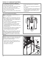
Filter in 

air handler 

cabinet

(Upflow  

Application)

A filter must be installed within the system.


A filter channel is provided in the unit, at the bot-


tom of the Blower/Filter compartment.
For customer ease of fil ter maintenance, it is 


recommended that a properly sized remote filter 
grill(s) be installed for units that are difficult to 
access. Airflow should not exceed the maximum 
rated velocity of the filter being used. 

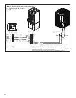
Cabinet Size*

A

B

C

Filter Size

16 x 20

20 x 20

22 x 20

* Cabinet size is indicated by the 7th digit in model number.

Table 16.1 Filter Sizes

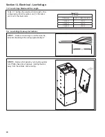
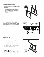
15.1 Remove the blower door panel. 

Section 15. Time Delay Switch Adjustment

Set the fan off delay setting using the Fan Delay 
Relay Switch (TDR) located on the blower control 
mounting plate located on the front of the blower. 

Factory default delay is 90 seconds.

90

0

Choke Coil
3/4 &1 HP 
motors only

Door Switch

Transformer

Fan Delay

Relay Switch

15.2 Time Delay Relay (TDR) Switch

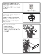
The Blower/Filter panel is removed using 1/4 turn 
thumb screws.

1.    Turn thumb screws on Blower/Filter panel.
2.   Pull top of panel out, away from cabinet.
3.   Lift panel up out of channel.
4.   Set aside.

Содержание GAM5 Series

Страница 1: ...R I approved matched indoor and outdoor systems Some of the benefits of installing approved matched indoor and outdoor split systems are maximum efficien cy optimum performance and the best overall s...

Страница 2: ...ection 9 Connecting the Duct work 21 Section 10 Refrigerant Line 22 Section 11 Refrigerant Line Brazing 23 Section 12 Condensate Drain Piping 26 Section 13 Electrical Low Voltage 28 Section 14 Electri...

Страница 3: ...an lead to the formation of condensate Condensate in the presence of chlorides and fluorides from paint varnish stains adhesives cleaning com pounds and cement creates a corrosive condition which may...

Страница 4: ...only in the first 3 4 of front bottom of unit in cross member Important Due to the unique design of this unit which allows the electrical wiring to be routed within the insulation do not screw cut or...

Страница 5: ...cabinet 3 Pull panel down and out of channel 4 Set aside To remove Heater Panel 1 Turn screws on Heater panel 2 Pull panel straight out away from cabinet 3 Set aside Removal of the Line Set panel is r...

Страница 6: ...8kW Breaker 24V Control 1 Ph A to C BAYEAAC08LG1A Electric Heater 8kW Lugs 24V Control 1 Ph A to C BAYEAAC10BK1A Electric Heater 10kW Breaker 24V Control 1 Ph A to C BAYEAAC10LG1A Electric Heater 10kW...

Страница 7: ...position it must be laid on its back marked REAR on carton Note To reassemble cabinet follow the steps in reverse order Ensure electrical connections are secure and the plug clips are engaged 4 1 Dis...

Страница 8: ...pread the top of the diverter slightly outwards and then pulling down and out through the blower opening as illustrated STEP 2 Disconnect the two wiring connections routed to the blower assembly STEP...

Страница 9: ...those wire harnesses STEP 6 Slide Coil assembly out of unit using built in coil support channels and set aside STEP 7 Use a 5 16 Allen wrench on the locking mechanism on each side of the bottom half...

Страница 10: ...10 1 2 STEP 8 Lift the Coil section up and away from the Blower section Set aside...

Страница 11: ...emove the top panel and all cross members Use a manual driver to avoid stripping screw holes Note Cross Members are removed by rotating them toward the door opening and then lifting up and out of the...

Страница 12: ...ions should metal strap ping be attached to the unit to be used as support mechanisms for carrying or suspension purposes Approved carrying 1 Hold by the cross members within the cabinet or unit top p...

Страница 13: ...nd Weight Model Number H x D x W in Blower Compartment in Unit Net Weight lbs GAM5A0A18H21SAA 50 x 22 x 17 1 2 22 120 GAM5A0A24H21SAA 50 x 22 x 17 1 2 22 120 GAM5B0A30H31SAA 52 x 22 x 21 22 133 GAM5B0...

Страница 14: ...ctory suitable for four way conversion They are shipped in the down flow orientation 6 2 Four Way Conversion Upflow Condensate Drains Refrigerant Connections Downflow Condensate Drains Downflow Config...

Страница 15: ...izontal Left Condensate Drains Low Voltage Connections inside unit Refrigerant Connections Horizontal Left Configuration Low Voltage Connections inside unit Horizontal Right Condensate Drains Airflow...

Страница 16: ...ve or utility room Review local codes to determine limitations if the unit is installed without a return air duct Ducted Return Non Ducted Return Supply Duct Plenum Accessory with safety guard CAUTION...

Страница 17: ...access for refrigerant lines Consider the overall space needed when external accessories are used additional height and width requirements may exist These units are not approved for outdoor installati...

Страница 18: ...to support the total weight of the unit accessories and duct work must be provided Isolate unit from the foundation using a suitable isolating material Typical Closet Installation 7 2 Upflow Installat...

Страница 19: ...The air handlers are rated for zero clearance from combustible materials STEP 1 Prepare the location site as appropriate for your application and per national state and local code requirements STEP 2...

Страница 20: ...Due to the unique design of this unit which allows the electrical wiring to be routed within the insulation do not screw cut or otherwise puncture the unit cabinet in any location other than the ones...

Страница 21: ...the air handler Reference ACCA Manual D Manual S and Manual RS along with the air handler Product Data and Service Facts for additional information Note Side return is not approved without Side Return...

Страница 22: ...n Sizes Model Vapor Line Connection Liquid Line Connection GAM5A0A18H21SAA 3 4 3 8 GAM5A0A24H21SAA 3 4 3 8 GAM5B0A30H31SAA 3 4 3 8 GAM5B0A36H31SAA 7 8 3 8 GAM5C0A42H41SAA 7 8 3 8 GAM5C0A48H41SAA 7 8 3...

Страница 23: ...rant connec tion stubs until ready to make connections STEP 2 Remove the plastic cap and Schrader valve core from the gas line STEP 3 Wrap the vapor sensor with a wet rag Important Care must be taken...

Страница 24: ...line 2 Wrap the Vapor Sensor with wet rag 3 Braze the refrigerant line connections Important Care must be taken during solder cap removal and brazing to avoid damage to unit compo nents STEP 8 Pressu...

Страница 25: ...es and indoor coil leak check and evacu ation are complete STEP 10 Evacuate until the micron gauge reads no higher than 350 microns then close off the valve to the vacuum pump STEP 11 Observe the micr...

Страница 26: ...r draining STEP 3 Connect 3 4 PVC pipe to the primary drain connection and the secondary drain connection if used using threaded drain nipples Use Teflon tape on the air handler drain line con nection...

Страница 27: ...oint temperatures may be met Optional depending on climate and application needs Provide a means of drainage to prevent winter freeze up of condensate line Optional depend ing on climate and applicati...

Страница 28: ...and to the thermostat Table 11 1 24 VOLTS WIRE SIZE MAX WIRE LENGTH 18 AWG 150 Ft 16 AWG 225 Ft 14 AWG 300 Ft 13 2 Low Voltage Hook up Instructions STEP 1 Route control wiring to unit Remove the exter...

Страница 29: ...nly Remove the control board completely from the control pocket Rotate the control board180 degrees Place the control board 4 6 inches back into the con trol pocket Attach wiring per appropriate hook...

Страница 30: ...er W1 W2 and W3 together if comfort control has only one stage of heat R to O jumper must be in place as shown for cooling only non heat pump systems for proper operation YI andYO connections must be...

Страница 31: ...Blue Black X2 Red Orange Heat Pump Red Yellow Orange Green White Blue Yellow Green White Blue B B Blue W G Y Y Yellow R Red O Orange O R B YI W1 YO G W2 W3 R Red O Orange W1 White SW1 410 22 1 2 3 SW1...

Страница 32: ...res are located within the wire pass through pro vided in the panel STEP 7 Slide control plate assembly into the control pocket until fully seated The control plate should be flush with the outer edge...

Страница 33: ...Connections STEP 1 Route High Voltage wiring to unit STEP 2 Select a conduit entry point 1 Select the entry point you will use to bring in your high voltage wiring 2 Remove plug from the entry point L...

Страница 34: ...or 1 1 2 conduit to conduit nut Note Reducing bushings may be required for your application STEP 4 Connect L1 L2 and ground wiring to pigtail harness and single green ground in Heater Compartment usin...

Страница 35: ...Filter Size 16 x 20 20 x 20 22 x 20 Cabinet size is indicated by the 7th digit in model number Table 16 1 Filter Sizes 15 1 Remove the blower door panel Section 15 Time Delay Switch Adjustment Set the...

Страница 36: ...36 Section 17 Unit Outline Drawing...

Страница 37: ...A6H5060E1 4A6B4061E1 4A6H5061E1 All other non rated matches must be charged per the nameplate charging instructions The following combinations should be charged to 8 degrees sub cooling to maintain ra...

Страница 38: ...ower disconnect s to apply power to the indoor and outdoor units STEP 4 Set the system thermostat to ON OFF DONE CANCEL ON OFF ON DONE CANCEL STEP 1 Make sure all panels are securely in place and that...

Страница 39: ...O terminal signals the EVC that the unit is in heat pump heating mode 4 Normally closed contacts on the EVC will pass 24VAC to the Yo terminal providing power to the outdoor unit control circuit 5 Th...

Страница 40: ...8 Be sure that the correct airflow setting is used Indoor Blower Motor 9 Operate complete system in each mode to verify proper performance Verify operation of supplemen tary electric heater Final pha...

Отзывы: