


18-CD20D1-18
9
Installer’s Guide
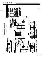
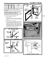
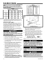
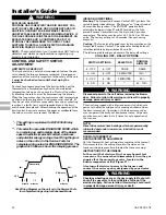
3. The side panels on upflow furnaces include locating
notches which may be used as guides for cutting an
opening for return air. Refer to Figure 12 and the
outline drawing on page 4 for duct connection dimen-
sions for various furnaces.
4. If a 3/4" flange is to be used for attaching the air inlet
duct, add to cut where indicated by solid lines in
Figure 12. Cut corners diagonally and bend outward to
form flange.
5. If flanges are not required, and a filter frame is installed,
cut along knockout guidelines.
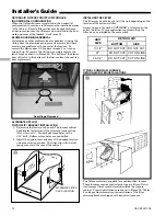
6.
Upflow Furnaces:
a filter rack is factory supplied for
bottom or side return. Use the filter rack on either side
or on the bottom if the filter is to be used within the
furnace cabinet.
When the upflow furnace is installed in the horizontal
right or left application and a return duct is attached to
the top side as shown in Figure 11, remove the filter
from the furnace and install in a remote location.
▲
WARNING
!
TO PREVENT INJURY OR DEATH DUE TO CONTACT
WITH MOVING PARTS, TURN THE POWER TO THE
FURNACE OFF BEFORE SERVICING FILTERS.
Do not install the filter in the return duct directly above
the furnace in horizontal applications.
When the upflow furnace is installed in the horizontal
right or left application and a close coupled (less than
36") return duct is attached to the bottom side of the
furnace as shown in Figure 11, securely attach a 1/2"
mesh metal hardware cloth protective screen to the
inside bottom of the filter grill
to prevent personal
injury from contacting moving parts when reach-
ing into the return opening to replace the filter.
Close coupled (less than 36") return (filter directly
beneath bottom side return) is not recommended due to
noise considerations.
Downflow Furnaces:
Brackets are factory supplied to
mount filters in the return air duct work.
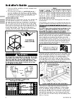
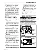
7. Connect the duct work to the furnace. See Outline
Drawing for supply and return duct size and location.
Flexible duct connectors are recommended to connect
both supply and return air ducts to the furnace.
If only the front of the furnace is accessible, it is recom-
mended that both supply and return air plenums are
removable.
8. When replacing a furnace, old duct work should be
cleaned out. Thin cloths should be placed over the
registers and the furnace fan should be run for 10 min-
utes. Don’t forget to remove the cloths before you start
the furnace.
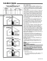
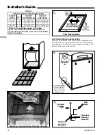
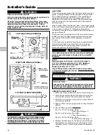
RETURN AIR FILTERS
TYPICAL UPFLOW RETURN AIR FILTER INSTALLATIONS
Filters are factory supplied for these furnaces. These fur-
naces require high velocity type air filters. The filters may be
located within the furnace blower compartment for UPFLOW
furnaces in either a BOTTOM or SIDE (left side or right side)
return air inlet. Some filters may need to be trimmed for
side or bottom filter use.
NOTE:
On upflow 5 or 6 ton airflow models, if the airflow require-
ment exceeds 1800 CFM, these models will require return
air openings and filters on both sides; OR 1 side and the
bottom; OR just the bottom.
▲
WARNING
!
Do not install the filter in the return duct directly above the
furnace in horizontal applications. Install the filter remotely.
Installing the filter directly above the furnace in horizontal
applications may cause property damage, serious injury or
death.
FILTER
REMOVE FILTER FROM UPFLOW
FURNACE WHEN RETURN DUCT IS
ATTACHED TO FURNACE TOP SIDE
(HORIZONTAL LEFT OR RIGHT
APPLICATIONS) AS SHOWN.
Close coupled (less than 36")
return (filter directly beneath bottom
side return) not recommended due to
noise considerations. If used, securely
attach 1/2" mesh metal hardware cloth
protective screen to the inside bottom of
filter grill.
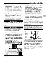
The upflow furnace blower door has a hinge at the bottom
which allows the door to tilt forward for filter replacement
without the door being removed. The furnace filter in the
bottom or side configuration can be removed by simply
turning the two latches on the blower door and tilting the
door forward.
The filter rails are spring loaded for automatic adjustment to
allow standard size, locally obtainable replacement filters.
The filter rack itself slides to adjust to the required width
needed for bottom or side return.
q
*
SEE OUTLINE DRAWING
w
LOCATING
NOTCHES
PROVIDED
FOR SIDE
RETURN
CUTOUT
*
*
*
*
CUT OUT
FOR
SIDE
FILTER
FRONT
of Furnace


