
18-CD20D1-18
21
Installer’s Guide
▲
WARNING
!
DO NOT attempt to manually light the burner. Failure to
follow this warning could result in property damage, per-
sonal injury or death.
START UP AND ADJUSTMENT
PRELIMINARY INSPECTIONS
With gas and electrical power “OFF”
1. Duct connections are properly sealed
2. Filters are in place
3. Venting is properly assembled
4. Blower door is in place
Turn knob on main gas valve within the unit to the “
OFF
”
position. Turn the external gas valve to “ON”. Purge the air
from the gas lines. After purging, check all gas connections
for leaks with a soapy solution —
DO NOT CHECK WITH
AN OPEN FLAME.
Allow 5 minutes for any gas that might
have escaped to dissipate. LP Gas, being heavier than air,
may require forced ventilation. Turn the knob on the gas
valve in the unit to the “ON” position.
LIGHTING INSTRUCTIONS
Lighting instructions appear on each unit. Each
installation must be checked out at the time of
initial start up to insure proper operation of all
components. Check out should include putting
the unit through one complete cycle as outlined
below.
Turn on the main electrical supply and set the thermostat
above the indicated temperature. The ignitor will automati-
cally heat, then the gas valve is energized to permit the flow
of gas to the burners. After ignition and flame is established,
the flame control module monitors the flame and supplies
power to the gas valve until the thermostat is satisfied.
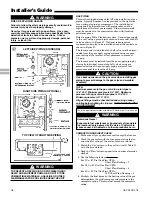
TO SHUT OFF
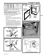
For complete shutdown: Move the control switch on the main
gas valve to the “OFF” position (See Figures 28 and 29).
Disconnect the electrical supply to the unit.
▲
CAUTION
!
If this is done during the cold weather months, provisions
must be taken to prevent freeze-up of all water pipes and
water receptacles. Failure to follow this warning could
result in property damage.
Whenever your house is to be vacant, arrange to have
someone inspect your house for proper temperature. This
is very important in below freezing weather. If for any
reason your furnace should fail to operate damage could
result, such as frozen water pipes.
▲
WARNING
!
FIRE OR EXPLOSION HAZARD
Failure to follow the safety warnings exactly could result in
serious injury, death or property damage.
Never test for gas leaks with an open flame. Use a com-
mercially available soap solution made specifically for the
detection of leaks to check all connections. A fire or
explosion may result causing property damage, personal
injury, or loss of life.
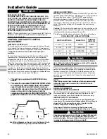
SEQUENCE OF OPERATION
Thermostat call for heat (2-stage thermostat)
Call for 1st stage only:
R and W1 thermostat contacts close signaling the control
module to run its self-check routine. After the control module
has verified that the 1st stage pressure switch contacts are
open and the limit switch(es) contacts are closed, the draft
blower will be energized.
As the induced draft blower comes up to speed, the pressure
switch contacts will close and the ignitor warm up period will
begin. The ignitor will heat for approx. 20 seconds, then the
gas valve is energized in 1st stage to permit gas flow to the
burners. The flame sensor confirms that ignition has been
achieved within the 4 second ignition trial period.
As the flame sensor confirms that ignition has been achieved,
the delay to fan ON period begins timing and after approx.
45 seconds the indoor blower motor will be energized at low
speed and will continue to run during the heating cycle.
Call for 2nd stage after 1st stage:
R and W2 thermostat contacts close signaling a call for 2nd
stage heat. After a 30 second delay, the induced draft blower
will be energized on high speed and the 2nd stage pressure
switch contacts will close allowing the gas valve to be energized
in 2nd stage and the indoor blower motor in high speed.
2nd stage satisfied, 1st stage still called:
R and W2 thermostat contacts open signaling that 2nd stage
heating requirements are satisfied. The induced draft blower
is reduced to low speed allowing the 2nd stage pressure
switch contacts to open and the gas valve is reduced to 1st
stage. After approx. 30 seconds the indoor blower motor is
reduced to low speed.
1st stage satisfied:
R and W1 thermostat contacts open signaling that 1st stage
heating requirements are satisfied. The gas valve will close
and the induced draft blower will be de-energized. The indoor
blower motor will continue to run for the fan off period (Field
selectable at 60, 100, 140 or 180 seconds - Factory setting is
100 seconds), then will be de-energized by the control module.
Thermostat call for heat (1-stage Thermostat)
R and W1/W2 (jumpered) thermostat contacts close signaling
a call for heat. 1st stage sequence of operation remains the
same as above. 2nd stage heat has a 10 minute delay from
the time of 1st stage ignition.
Thermostat satisfied:
R and W1/W2 (jumpered) contacts open signaling the control
module to close the gas valve and de-energize the induced
draft blower. The indoor blower motor will continue to
operate at high heat speed for approx. 30 seconds after the
flames are extinguished and then is switched to low heat
speed for the remaining FAN-OFF period.
INDOOR BLOWER OPERATION WITH THERMOSTAT FAN
SWITCH “ON”:
Fan is R-G.
R-W energized, fan continues to run without interruption.
Heat Low speed if it is a two stage furnace.
Heat speed if it is a single stage furnace.


