background image


39 

TRAK Machine Tools 

Southwestern Industries, Inc. 

32240 - Printer and MMS - Installation & Printing Guide 


4.6.1.3


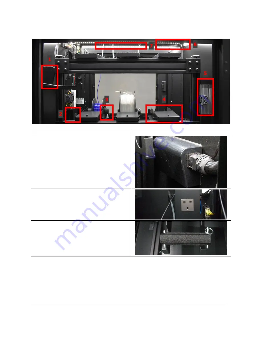
Inside View 


Description 

Image 

1.


HEPA Filter 


Integrated HEPA filtration with activated 
charcoal stage to control VOCs. 

 
NOTE


 It is recommended to replace the 

filter quarterly. 


2.


Print Server Power Supply 


The MMS provides power for the Print 
Server within the cabinet.


3.


Spool Holder & Pin 


Holds the Spool on the Spool Holder 
Bracket.


Содержание 3ntr Series

Страница 1: ...al Covers Current Models 3ntr A2v4 3ntr A4v4 MMS v2 2615 Homestead Place Rancho Dominguez CA 90220 5610 USA T 310 608 4422 F 310 764 2668 Service Department 800 367 3165 e mail sales trakmt com service trakmt com web www trakmt com Document P N 32240 Version 122220 ...

Страница 2: ...stem MMS 12 3 4 Electrical Requirements 13 4 0 Installation Process 14 4 1 Lifting Moving Uncrating and Unpacking 14 4 1 1 Lifting Moving before Uncrating 14 4 1 2 Unpacking 14 4 1 3 Lifting Moving after Uncrating 14 4 2 General Packing List 15 4 3 A2 A4 3ntr 3D Printers 16 4 3 1 Orientation Controls Functions 16 4 3 1 1 Front View 17 4 3 1 2 Rear View 19 4 3 1 3 Internal View 22 4 3 2 Installing ...

Страница 3: ... 7 1 1 Front View 49 4 7 1 2 Rear View 50 4 7 2 Connecting the Cables Powering ON 50 4 8 Repetier Server Overview 54 4 8 1 Navigation Bar 54 4 8 2 Dashboard 55 4 8 3 Printer Control Management 56 4 8 3 1 Print Tab 57 4 9 MMS Dashboard 58 4 9 1 MMS Summary 60 5 0 Printing 62 5 1 Pre Printing Steps 63 5 1 1 Verify all printer maintenance is up to date 63 5 1 2 Verify correct file is loaded onto SD C...

Страница 4: ...d Plate 89 5 4 6 Purge the Nozzles 89 5 4 6 1 Purge Procedure 90 5 5 Printing 91 5 5 1 Print from an SD Card 91 5 5 2 Print from the Print Server 91 5 5 2 1 Direct Print 91 5 5 2 2 Upload G Code 91 5 6 Post Printing 93 5 6 1 Wait for Build Plate to cool 93 5 6 2 Wipe Build Plate with Alcohol 93 5 6 3 Turn HEPA Filter Off 93 5 7 Post Processing 93 TRAK Warranty Policy 94 ...

Страница 5: ...____ SSI Product Key 2 ____________________________ Computer Name Location ___________________________ SSI Product Key 3 ____________________________ Computer Name Location ___________________________ KISSlicer Product Key 1 ____________________________ Computer Name Location ___________________________ KISSlicer Product Key 2 ____________________________ Computer Name Location ___________________...

Страница 6: ...and VOC s you come in contact with Always close the print chamber door and turn on the HEPA Filter while printing 1 2 Safety Labels Notices as Used in this Manual DANGER Immediate hazards that will result in severe personal injury or death WARNING Hazards or unsafe practices that could result in severe personal injury and or damage to the equipment CAUTION Hazards or unsafe practices that could re...

Страница 7: ...ls removed Never reach inside of the 3ntr A2 A4 while in operation Do not lean on the machine while it is running Always follow OSHA and workplace electrical safety guidelines when working with these products as there is a static current and users should be cautious Prevent slippage Keep the work area dry and clean Protect your eyes Wear approved safety glasses with side shields at all times Don t...

Страница 8: ...ear the final location b Uncrate and unpack printer MMS c Lift and move the printer MMS after uncrating 3 Review Packing List Report any missing items immediately Write down Product ID s for SSI KS in the Additional Comments Section 4 Printer Installation a Review Orientation Controls and Functions b Install Spool Holder on the Back of the Printer c Connect the cables Power ON d Review LCD Display...

Страница 9: ...eat bridge and nozzle e Install Extruder Assembly f Torque nozzles i Hardened Nozzles Torque while hot use Unload Filament function g Perform Z nozzle height comparison h Install adapter holding bracket i Check extruder gains match the gains value in printer s Hardware Menu j Auto home Check for Z Nozzle Height from the Build plate using feeler gauge i 0 4mm gap standard for 0 4mm nozzle 2 Load Fi...

Страница 10: ...size 4 Basic Set up Steps a Verify the correct material type is loaded b Verify filament quantity c Verify the filament feed path is clear d Turn HEPA Filter on e Check the Build Plate f Purge the nozzles you plan to use if no material change is required 5 Printing a Print Benchmark Part 1 from an SD Card or the Print Server Day 2 Training Check Steps 1 Review Printed Part from Day 1 2 Post Printi...

Страница 11: ... type b Verify you are using the correct nozzle size 4 Basic Set up Steps a Verify the correct material type is loaded b Verify filament quantity c Verify the filament feed path is clear d Turn HEPA Filter on e Check the Build Plate f Purge the nozzles you plan to use if no material change is required 5 Printing a Print your Benchmark Part 2 from an SD Card or the Print Server Additional Items Che...

Страница 12: ...pping Dimensions 35 x 42 x 52 890 x 1067 x 1320 mm 24 5 x 26 5 x 38 3 622 x 673 x 973mm 45 5 x 38 3 x 42 3 1156 x 973 x 1074 mm Shipping Weight 498 lbs 226kg 152 lbs 69 kg 370 lbs 168 kg Heated Print Bed Anticorodal aluminum 6082 Removable Reusable Tray Yes Steel Cabinet Frame Construction 0 08 2 mm Powder Coated Clear Panels Polycarbonate Printing Specifications Printer Build Volume 23 6 x 11 8 x...

Страница 13: ...50mm Y x 500mm 23 622 X x 13 77 Y x 19 68 X 310 5 Y 201 3 1 1 2 A4v4 Nozzle Configuration Volume Metric Volume Imperial Bed Center Metric 3 Nozzle 3 Nozzle Prints 1 2 3 295mm X x 156mm Y x 200mm 11 61 X x 6 14 Y x 7 87 X 148 Y 127 3 Nozzle 2 Nozzle Prints 1 2 or 2 3 295mm X x 180mm Y x 200mm 11 61 X x 7 08 Y x 7 87 X 148 Y 119 5 Y 140 5 3 Nozzle 1 Nozzle Prints 2 295mm X x 204mm Y x 200mm 11 61 X ...

Страница 14: ...Requirements This section has dimension information for the A2 A4 and Material Management System MMS 3 3 1 A2 Printer CAUTION Always maintain a 24 clearance in order to access the printer for maintenance If performing maintenance while printer is powered on please see your local regulations on how much clearance you must provide ...

Страница 15: ...11 TRAK Machine Tools Southwestern Industries Inc 32240 Printer and MMS Installation Printing Guide 3 3 2 A4 Printer ...

Страница 16: ...12 TRAK Machine Tools Southwestern Industries Inc 32240 Printer and MMS Installation Printing Guide 3 3 3 Material Management System MMS ...

Страница 17: ...e about any electrical wiring A2 A4 110v A4 220v MMS AC Input 220 230 VAC 15A 110 120 10A 220 230 VAC 10A 220 230 VAC 15A TRAK supplies you with one of two plugs depending on whether you ordered a printer that runs on 110v or 220v Supplied by TRAK for 220v Supplied by TRAK for 110v For 220v devices the customer is responsible for providing the L14 20R socket prior to the installation If you do not...

Страница 18: ...ove cover packaging foam bubbles packaging side panels Steps 1 Use a forklift or fork pallet to move the printer MMS unit as close as possible to the final location before uncrating or removing from the pallet 2 Remove shipping screws holding top portion of printer shipping crate to base Lift off the top portion of shipping crate from base 3 Remove contents of printer MMS and place on table 4 Remo...

Страница 19: ...tems Hex Bit 2 5mm Socket 7mm Wrench 7mm Coolant Refill Bottle Fuse AC Power 15 Amps Kit of 2 Allen Wrench Set Pick Hook Set Kit of 4 Brass Wire Brush Cutter 5 Long Aluminum Pencil Sharpener Dynamometric Screwdriver Additional Items If no MMS was ordered External HEPA Filter Power Supply Feeder Hose to Printer MMS Purchase optional If you purchased an MMS below is the list of additional items you ...

Страница 20: ...parts that might not apply to you depending on whether you purchased an MMS or not The green sections are required to read regardless of what you ordered The blue and orange depend on what you ordered See diagram below to understand what sections apply to you and in what order you should read them 4 3 1 Orientation Controls Functions Whether you purchased an A2 or an A4 everything is almost the sa...

Страница 21: ...ost of your maintenance from Component Description Image 1 Webcam The webcam is great for remotely monitoring prints progress documenting the printing process making time lapse videos but also to see if something went wrong with the print and be able to review when the print failed 2 E Stop Push the E Stop button if you need to stop the printer immediately in the event of an emergency You can also...

Страница 22: ...s change values control printer Jog Wheel Button Push to select the menu option 5 Door Handle The door handle can be locked using the pair of keys it comes with 6 Front Door The printer s front door gives you access to the Print Chamber Print Bed Nozzles and more It should always be shut during a print to reduce the contact with any harmful Volatile Organic Compounds VOCs Enclosures for 3D printin...

Страница 23: ...grams in and changing out the spools Component Description Image 1 SD Card Slot This is where you insert your SD card Your SD Card should come loaded with a Software Tools folder You can also add any g code files you would like to print 2 Side Panel Fan Helps keep the control board and side panel cool 3 Coolant Reservoir Holds the coolant which can come in red clear or blue The coolant helps contr...

Страница 24: ...r which gets hot when the coolant pulls the heat from the nozzles 6 Printer Power Inlet and Power Switch Left Printer Power Inlet w o MMS o The Printer Power Cord plugs in here and connects to the power supply from the wall w MMS o The Printer Power Cords plugs in here but connects to the MMS Power Plug below Right Power ON OFF switch 7 Locking Collar The Locking Collar holds the Filament Spools i...

Страница 25: ... Knob o The Feeder Sensor detects if filament has run out and will pause the print o The Feeder Gear and Stepper Motor work together to push the filament forward toward the Extruder o The Feeder Pressure Knob is used to adjust the filament feeder pressure 11 Feeder Unit This is where the filament enters the Feeder Assembly 12 MMS Power Inlet If you purchase an MMS with your printer then this is th...

Страница 26: ...tion Image 1 Nozzles The nozzle is a precision piece of metal where melted filament is extruded out from Nozzles are interchangeable and come in various sizes 0 4 mm is normal while you might use a smaller nozzle for finer detail or a larger nozzle to print faster 2 Z Sensor Assembly During homing the Z sensor arm swings over the build plate and sends a signal when the plate is at the right height...

Страница 27: ...ing the Spool Holder to the Back of the Printer From the Back of the Printer Images 1 Grab the Spool Holder and long screw that was shipped out to you 2 Locate the coupling nut where you want to install the Spool Holder on the back of the printer NOTE There are four coupling nuts on the back of the printer 3 Fit the Spool Holder around the coupling nut and then insert the long screw into the spool...

Страница 28: ...u purchased an MMS skip over to the LCD Overview section The Material Management System section will show you how to connect your printer MMS to a power source Step Image FOR 110v ONLY 1 Grab the 110v power cord that was supplied to you FOR 220v ONLY 2 Grab the power cord provided to you with your printer 3 Plug the power cord to the socket at the back of the printer FOR 110v ONLY 4 Plug the power...

Страница 29: ...el SPFU presence if installed Filament sensor enabled F Filament has run out Elapsed print time of current print o Row 4 Status Line Shows you the current printer status Prepare Contains the main printer functions and is only available when the printer is not actively printing o Main go back to main menu o Change Filament This function is used when you are changing filaments of the same material a...

Страница 30: ...you to initialize the SD Card o Hardware This menu allows you to change the following configuration settings such as SPFU nozzle size Hi Std Temp Calibration values and more Statistics Displays the print time elapsed and amount of filament extruded o On Time elapsed o F Amount of filament extruded Printing Main Menu Info Screen Displays printer printing information o Row 4 Comment Line shows vario...

Страница 31: ...From the Info Screen go to Main Menu Prepare Menu Preheat Chamber 2 The print chamber will begin to heat up to 65 C Target Temperature is set to 65 C 4 3 5 3 Auto Home On the LCD Screen 1 From the Info Screen go to Main Menu Prepare Menu Auto home 2 The nozzles will position itself to the front leftmost section of the print chamber Target Position X Axis 0 00 mm Target Position Y Axis 0 00 mm 3 Th...

Страница 32: ...go to Main Menu Prepare Menu Move Axis 2 Select the incremental amount that you want to move the axis by 3 Select the axis you want to move CAUTION ALWAYS move the Z axis down before moving the X Y axes Not moving the Z axis down may result in the nozzles scratching the build plate 4 The printer will now start to move in the positive direction that you selected To reset use the Auto Home function ...

Страница 33: ...tion NOTE There are two versions of the Raspberry Pi Raspberry Pi 3 B Raspberry Pi 4 B 4 4 1 Orientation Controls Functions 4 4 1 1 Front View Raspberry Pi 3 B Description Raspberry Pi 4 B Description 1 Ethernet Port USB Port For Mouse Keyboard 2 USB Port For Mouse Keyboard USB 3 0 Port For Flash Drive 3 USB Port For Flash Drive USB Port For Webcam 4 USB Port For Webcam USB 3 0 Port For Printer 5 ...

Страница 34: ...ading operating system and data storage 2 Status Lights n a 4 4 2 Connecting the Cables Powering ON In this section you will learn the steps to power on your Raspberry Pi NOTE Raspberry Pi 4 B is referenced in the instructions but it is applicable to Raspberry Pi 3 B Step Image 1 Grab the cables provided to you with your print server 2 Connect the cables as shown a USB Receiver for Wireless Mouse ...

Страница 35: ...pending on what version of the Raspberry Pi that you have you now need to connect the following cables to the side of the Print Server a Power Cord b HDMI Raspberry Pi 3 B or Micro HDMI Raspberry Pi 4 B 8 Connect the other end of the Raspberry Pi Power cord to your facilities 110v power socket 9 Connect the other end of the HDMI cable to the back of the LCD Monitor 10 Connect the power cord for th...

Страница 36: ...llowing display on your monitor 15 Click on the Firefox web browser 16 The Repetier server dashboard should be your home page on the Firefox web browser NOTE The server is shipped out already configured to your printer so it should look like the screen on the right If you do not see your printer on the dashboard or if the page is blank try refreshing the page and or pressing the home button ...

Страница 37: ...ge Filter HEPA 0 5 um Active Carbon VOC Barrier Power Requirement Input 110 230VAC Output 12VDC 1 5A 18W Airflow 25 m3 h peak Noise 48db Weight 3 5 Kg 4 5 1 Orientation Connecting the Cables Powering ON Description Image 1 Display Displays usage Hours The total number of hours the HEPA Filter has been used powered on 2 HEPA Filter Tube Connect one end of the tube to the back of the printer as show...

Страница 38: ...ay should be powered on the green button should be lit bright green and you should hear the light sound of the HEPA filter running 5 HEPA Filter The filter is maintained within the body of the cannister NOTE It is recommended that the filter be replaced annually 4 5 2 Placement We recommend placing the HEPA Filter in a secure location near the printer If you have or purchased a printer stand cart ...

Страница 39: ...printer from a humidity controlled environment which ensures optimum print quality and part performance With the server installed and connected to your network both the browser based remote dashboard and the touchscreen on the MMS will display live material quantity readouts in meters or grams for each of 6 spools of material 4 6 1 Orientation Controls Functions In this section you will learn abou...

Страница 40: ...ower the built in heater ON OFF you must use the switch on the side of the MMS 4 HEPA Filter Vent The HEPA Filter Vent is where the VOC filtered air will come out of the MMS 5 MMS Power Inlet Power Switch Power Inlet The MMS requires only one 220V connection for the cabinet which supplies the correct power and voltage to the printer the print server and the web camera Power Switch In order to powe...

Страница 41: ...37 TRAK Machine Tools Southwestern Industries Inc 32240 Printer and MMS Installation Printing Guide 7 Door Handle The door handle provides access to the front side of the MMS cabinet 4 6 1 2 Rear View ...

Страница 42: ...bcam keyboard and mouse 3 Ethernet Port The MMS Provides you with an Ethernet Port for the Print Server to get connected to your network so you could access your MMS online 4 HDMI Port The MMS Provides you with an HDMI Port for you to be able to connect a monitor to the print server 5 Additional USB Ports 2 2 USB ports on the left side These are additional USB ports for you to use for anything els...

Страница 43: ...iew Description Image 1 HEPA Filter Integrated HEPA filtration with activated charcoal stage to control VOCs NOTE It is recommended to replace the filter quarterly 2 Print Server Power Supply The MMS provides power for the Print Server within the cabinet 3 Spool Holder Pin Holds the Spool on the Spool Holder Bracket ...

Страница 44: ...er Guides are fed through the MMS and they help protect the filament traveling from the MMS to the printer safe from moisture dust oil and physical damage 4 6 2 Installing Desiccant Cannister Holders Two desiccant cannisters are provided to you for your MMS in order to manage the humidity within the cabinet Step Image 1 Hang one desiccant cylinder tray inside the front door on the front of the sca...

Страница 45: ...at steps 1 2 until all six Strain Relief Flex Collars have been installed 4 Now that all six Strain Flex Relief Collars are installed it is time to install the Bowden Tubes 5 The Bowden Tubes can be pushed right through the Strain Relief Flex Collars If they do not fit you can loosen the nut slightly in order to get it the tube through NOTE You may leave the nut loose enough to push and pull tube ...

Страница 46: ... end of the HEPA Filter Tube and push it into the elbow connected to the side of the MMS 3 Your HEPA Filter Tube is now connected 4 6 5 Connecting the Cables Powering ON In this section you will learn how to connect the cables in order to power on your MMS and printer Step Image 4 Grab the two power cords that were provided to you 5 Grab the power cord that goes from the MMS to the 220v receptacle...

Страница 47: ...20v receptacle L14 20R 8 Now grab the power cord that goes from the printer to the MMS 9 Connect the male end to the top of the MMS 10 Connect the female end to the back of the printer 11 Now you re ready to start powering on the printer and MMS 12 Flip the power switch ON on the Printer 13 Turn the E Stop button clockwise to power on the printer ...

Страница 48: ...E Your MMS LCD Display will not turn on until your print server has been installed and powered on 16 One quick way to know if your MMS is powered on is by checking to see if the LED lights turn on inside the cabinet 4 6 6 LCD Display and Menu Overview In this section we will go over the LCD Display on the Material Management System MMS Description Image 1 System Menu This menu contains the followi...

Страница 49: ...ilament Weight This is the weight of the filament only 7 Loaded Status This displays the status of the Spool Holder bracket if it has material loaded or not 8 MMS Temp internal This lets you know the current temperature Celsius inside the cabinet 9 Relative Humidity This lets you know the current Relative Humidity within the cabinet 10 Remaining Filament Display This button selects the remaining f...

Страница 50: ...creen should be very near the negative empty reel weight specified by the server the default empty reel weight for a 2kg reel is 0 960 kg when the appropriate empty reel is installed the value should be near zero 4 6 9 Calibrating the MMS Calibrating the MMS should always be done after you Zero the Cabinet Calibrating the cabinet ensures you have the correct amount of material accounted for and pr...

Страница 51: ... reference on the channel spool holder bracket one at a time for weighing Item 1 on the screen is the calibration reference you entered Item 2 on the screen displays the channel you would place the spool on Item 3 on the screen is the current weight on the channel 7 Let the channel reading settle takes about 5 10 seconds 8 Press Commit to save the calibration Repeat for each channel until all chan...

Страница 52: ...n Printing Guide 4 6 10 Setting the Box Temp To set the Box Temp is to set the temperature of the MMS cabinet Steps Image 1 From the main screen touch the MMS Temp 2 Enter the desired cabinet temperature In this example we entered 35 0 C 3 Press Enter 4 You have now set your Box Temp ...

Страница 53: ...Model ML350G 10 Hardware Line Fanless Industrial Input Voltage 9 24 VDC Environment Operating temperature 0 C 50 C Operating temperature for UL listed configurations 0 C 40 C Operation humidity 10 90 Storage temperature 0 C 60 C Storage humidity 5 95 Primary Storage 128 GB mSATA SSD Mounting Wall DIN VESA 75 100 Additional mounting hardware required 4 7 1 Orientation Controls Functions 4 7 1 1 Fro...

Страница 54: ...4 USB Port For Mouse Keyboard 5 USB Port For Webcam 6 USB Port For Flash drive 7 DisplayPort Connect to the monitor using the DP to HDMI cable 4 7 2 Connecting the Cables Powering ON Step Image 17 Connect the power cord to the back of the Print Server 18 Then connect the other end to the power socket inside the MMS You were provided two ethernet cables Take one of them and 19 Connect one end of th...

Страница 55: ...ake the other end and connect it to your facilities modem router data jack 23 Connect the USB Receiver for the Wireless Mouse Keyboard to the front of the Print Server 24 Power ON your mouse keyboard 25 Place the webcam on the front window panel 26 Connect the USB cable for the webcam to the back of the MMS 27 There should be an extra male to male USB cable Take one end and connect it to the insid...

Страница 56: ...I port in the back of the MMS 32 Connect the other end to the back of the LCD Monitor provided to you 33 Grab the power cord for the LCD Monitor and connect the power cord to the back of the monitor 34 Connect the other end to your facilities power supply socket 35 Power on your LCD Monitor You were provided a USB to Printer Port cable 36 Connect the Printer Port end to the back of the printer 37 ...

Страница 57: ...as powered on you should see the following screen on your monitor Please see next section on how to establish a connection with your printer and MMS 45 Click on the Firefox web browser 46 The Repetier server dashboard should be your home page The server is shipped out already configured to your printer so it should look like the screen on the right NOTE If you do not see your printer on the dashbo...

Страница 58: ...6 Settings Takes you to the main configurations and to see the full manual 7 Language Let s you select your preferred language Extra Icon for Linux Some servers like the Raspberry Pi and other embedded devices are very popular These normally run under Linux and have limited resources The icon is meant to monitor these resources and warn on possible problems early Under the extra icon the CPU load ...

Страница 59: ...raph to Webcam View 3 Light mode Dark mode Autodetect Light Mode and Dark Mode 4 Add Printer and Upload Printer Configuration button allows you to add another printer device Not recommended 5 Memory Bar The most important thing just above the printer s mini windows the free disk space must be always be bigger than 5 6 GB If you happen to have too many files you may want to do periodic purging of o...

Страница 60: ...rride Not recommended for use 4 Fan Speed Override Not recommended for use 5 Extruder Temperature Override Not recommended for use 6 Print Bed Temperature Override Not recommended for use 7 Menu a Deactivate Printer Disconnects the printer from the server b Connection Information Provides the data stream statistics The most valuable information here is the errors c Printers EEPROP not recommended ...

Страница 61: ...er 4 Search Use to search for G Code files parts 5 Action Lets you add rename or delete groups You can also use this function to delete all the parts in a group but the action cannot be undone Use with caution 6 View Mode Lets you change the view mode for your save G Code Files parts 7 Preview List of the G Code Files saved onto the server a Print Part Immediately starts the printing process b Inf...

Страница 62: ...and reel information After you make changes on the MMS Dash Page the cabinets touchscreen will prompt you to confirm that the changes have been made on the printer to ensure that the actual set up matched the MMS Servers Data Step Image 1 Print Server s IP Address To Access the MMS Dashboard enter the Print Servers IP address followed by 3000 for example 100 1 100 85 3000 2 Summary Button Takes yo...

Страница 63: ...imations 7 MMS Information Unit Name You can change the name of the MMS Relative Humidity Gives you the current cabinet humidity percentage for the MMS Box Temperature Gives you the current cabinet temperature for the MMS 8 Nozzles The nozzle information in the MMS Dash is there as a convenient reference to exactly how your printer is configured and must be input or changed any time the nozzles or...

Страница 64: ... you can retrieve all the latest news from Plural and submit any support tickets 10 Reel Information After entering your material information you can enter reel weight information so that you can better track your remaining filament 4 9 1 MMS Summary The MMS Summary is where you can find a summary of your nozzles and reel setup ...

Страница 65: ... Humidity Give you the current cabinet humidity percentage for the MMS 8 Box Temperature Gives you the current cabinet temperature for the MMS 9 Nozzle Configuration Gives you a summary of the three nozzle configurations so you know the Nozzle Diameter and Material Diameter 10 Reel Configuration Gives you the current material information for each spool stored in the MMS including the extruder it i...

Страница 66: ...ck Material Changes If a material change is needed 1 Unload Load Change Filament with and without MMS 2 Clean the Nozzles Check Nozzle Changes 1 Verify you are using the correct nozzle type 2 Verify you are using the correct nozzle size Check Basic Set up Steps 1 Verify the correct material type is loaded 2 Verify filament quantity 3 Verify the filament feed path is clear 4 Turn HEPA Filter on 5 C...

Страница 67: ...hit print you should double check that the correct file was loaded onto the SD Card or Print Server most of the time you can just cross reference the file name 5 2 Material Changes This section of the printing process applies only if materials need to be changed If a material change is required there are two different ways you can go about changing it Option 1 If loading the same material type and...

Страница 68: ...t and then retracts the filament Status Line 6 The Status Line will display Change fil _ now once the purge is complete Status Line 7 Remove the purged filament Back of the Printer 8 Push the Feeder Handle down to disengage the Feeder Mechanism You may use the Locking Tab to lock the Feeder Mechanism in the pushed down position 9 Remove the Filament from the Feeder Unit rewinding it back on the Sp...

Страница 69: ...ip from the side of the spool where it is secured NOTE New spools have the filament secured to the spool with a zip tie Avoid letting go of the filament tip until it is inside the feeder unit to prevent de coiling 16 Trim off several millimeters off the Filament Tip at an angle to point the tip and remove any damage 17 Push the Feeder Handle down to disengage the Feeder Mechanism You may use the L...

Страница 70: ... Status Line 22 The Status Line will display Change _ completed once the priming is complete Status Line 23 Verify the filament was purged If not purge the filament again 24 Remove the purged filament from the inside of the printer 25 You have successfully changed the filament 5 2 1 2 Unloading Filament From the LCD Images 1 Before unloading filament always check that there is enough clearance abo...

Страница 71: ...7 The Status Line will display Unload _ Completed once the purge is complete Status Line 8 Remove the purged filament Back of the Printer 9 Push the Feeder Handle down to disengage the Feeder Mechanism You may use the Locking Tab to lock the Feeder Mechanism in the pushed down position 10 Remove the Filament from the Feeder Unit rewinding it back on the Spool 11 Thread the Filament Tip to the side...

Страница 72: ...eeding straight to the extruder 3 Replace the Locking Collar on the Spool Holder Only a small amount of friction is needed against the spring to keep the filament from de coiling 4 Remove the Filament Tip from the side of the spool where it is secured NOTE New spools have the filament secured to the spool with a zip tie Avoid letting go of the filament tip until it is inside the feeder unit to pre...

Страница 73: ...CD Screen 9 Before loading filament always check that there is enough clearance about 50mm between the nozzle and the build plate 10 Press the black Jog Wheel button to go to the Main Menu 11 Then go to Prepare Menu Purge Filament Main Menu Prepare Menu 12 Select the nozzle that you want to purge the nozzle you loaded filament into Purge Filament Menu 13 The Status Line will display Heating as the...

Страница 74: ...black Jog Wheel button to go to the Main Menu Then go to Prepare Menu Change Filament Main Menu Prepare Menu 8 Select the nozzle that you want to change filament from Change Filament Menu 9 The Status Line will display Heating as the printer heats the selected nozzle to 245 C Status Line 10 The Status Line will display Purging _ as it purges some filament and then retracts the filament Status Line...

Страница 75: ...feeding straight to the extruder 18 Replace the Pin and place the Spool Holder back on the Bracket 19 Remove the Filament Tip from the side of the new spool where it is secured NOTE New spools have the filament secured to the spool with a zip tie Avoid letting go of the filament tip until it is inside the feeder unit to prevent de coiling 20 Trim off several millimeters off the Filament Tip at an ...

Страница 76: ... printer 28 You have successfully changed the filament 5 2 2 2 Unloading Filament From the LCD Images 1 Before unloading filament always check that there is enough clearance about 50mm between the nozzle and the build plate before starting 2 Press the black Jog Wheel button to go to the Main Menu Then go to Prepare Menu Unload Filament Main Menu Prepare Menu 3 Select the nozzle that you want to un...

Страница 77: ...ck on the Spool 10 Thread the Filament Tip to the side of the spool to avoid de coiling 11 Remove the Spool Holder from the Spool Holder Bracket and remove the Pin 12 Remove the Spool from the Spool Holder 13 Replace the Pin and place the empty Spool Holder on the Bracket Back of the Printer 14 Remove the Filament Feeder Guides from the Feeder Unit and hold them to the back of the printer with the...

Страница 78: ...aterial into Ex Feeder 3 goes to Extruder 3 2 Push the Feeder Handle down to disengage the Feeder Mechanism You may use the Locking Tab to lock the Feeder Mechanism in the pushed down position If applicable 3 Feed the Filament Feeder Guide from the inside of the MMS Feeders Strain Relief Flex Collars Leave it about 2 inside the MMS 4 Connect the Filament Feeder Guides to the Feeder Unit ...

Страница 79: ...OTE New spools have the filament secured to the spool with a zip tie Avoid letting go of the filament tip until it is inside the feeder unit to prevent de coiling 9 Trim off several millimeters off the Filament Tip at an angle to point the tip and remove any damage 10 Feed the Filament from the inside of the MMS through the Filament Feeder Guide and through the Feeder Unit until it reaches the Ext...

Страница 80: ...ne 18 The Status Line will display Purge _ Completed once the purge is complete Status Line 19 Verify the filament was purged If not purge the filament again 20 Remove the purged filament from the inside of the printer 21 Your nozzle is now ready to use 5 2 3 Nozzle Cleaning Operation Cleaning the nozzles is highly recommended after each material change but most importantly if you re changing to a...

Страница 81: ...the Feeder Handle down to disengage the Feeder Mechanism You may use the Locking Tab to lock the Feeder Mechanism in the pushed down position 2 Trim off several millimeters off the Filament Tip at an angle to point the tip and remove any damage 3 Feed the Cleaning Nylon through the Feeder Unit until it reaches the Extruder 4 Release the Feeder Handle to engage the Feeder Mechanism If you used the ...

Страница 82: ...tus Line 11 The Status Line will display Heating as the printer heats the selected nozzle to 245 C Status Line 12 The Status Line will display Heating Done once it is heated and start to purge the cleaning nylon 13 Once the purge is complete the nozzle will begin to cool down until it reaches 140 C then it will retract the filament from the nozzle tip Status Line At the front of the printer 14 Rem...

Страница 83: ...int is critical Nozzle Types The nozzle type can have a large impact on the quality of your print as well as how quickly you have to replace the nozzles Before you print you should verify that you are using the correct nozzle type based on the material required for the print Nozzle Sizes Nozzle sizes can have a huge impact on print quality surface finish and print time Before you print make sure t...

Страница 84: ...ing hardened nozzles torque the nozzles while they re hot Use the Unload Filament function to heat up the nozzles 8 Using a feeler gauge ensure that there is a gap between the nozzles and the build plate of approximately 0 5mm 9 Use the Move Axis function to move the Z axis up to 142mm 10 Place the Dial Indicator on its stand and place it underneath nozzle 1 11 Reset the dial indicator so that the...

Страница 85: ...a dial indicator reading for each nozzle The recommended tolerance between Nozzle 1 3 is 0 02mm The recommended tolerance between Nozzle 1 2 or Nozzle 2 3 is 0 01mm If the nozzle heights are not within the tolerances listed above they will need to be re calibrated If the nozzles heights are within tolerance move on to Calibration Prints skip Adjust your Z Nozzle Height Adjust your Z Nozzle Height ...

Страница 86: ...Tube Adapter to be purchased 5 Remove the screws on the Adapter Bracket highlighted as item 1 on the image to the right 6 Remove the Adapter Bracket highlighted as item 1 on the image to the right This will provide you with access to the Tube Adapters labeled as item 2 on the image to the right 7 Loosen only the screws for only the nozzles that need adjustment labeled as item 3 on the image to the...

Страница 87: ... that nozzle and then tighten the Tube Adapter to lock it into place 11 Place the Adapter Bracket back on and tighten the screws 12 Connect the Bowden Tubes back onto the Tube Adapter 13 Reconnect the Pin Head Connector 14 Replace the top cover and secure it into place using the screws Feel free to run the Z_Comparison gcode file again if you would like to ensure the heights are within tolerance 1...

Страница 88: ...s Load the material now before moving onto the next step NOTE We recommend loading 3 highly contrasting colors in order to be able to see the calibration prints clearer For example in Extruder 1 load black white or grey And in extruder 2 and 3 load different contrasting colors To complete the Z Offset Calibration Print 2 From the LCD go to Prepare Software Tools A2 or A4 depending on what machine ...

Страница 89: ...efore the Z offset value is 1 To record the Z Offset value 4 From the LCD go to Prepare Menu Hardware Calibration Offset Z Main Menu Prepare Menu Hardware Menu Calibration Menu 5 Enter the Z Offset reading In this example it is 1 so you would turn the black jog wheel counter clockwise until you see 1 Press the black jog wheel button to record the offset value 6 Once the value is entered go back to...

Страница 90: ... calibration print XY Calibration Print 10 From the LCD go to Prepare Software Tools A2 or A4 depending on what machine you have Service XY_Ext_2 3 gcode Main Menu Prepare Menu Software tools Folder A4 Folder Service Folder The XY calibration print takes approximately 42 minutes to print and should look similar to the image on the right ...

Страница 91: ...set values To read the offset values see image below NOTE The axes on the calibration print are flipped The vertical line is the X Axis Offset and the horizontal line is the Y Axis Offset The large bumps on the print are zeroes As you move down left the numbers go in the negative direction As you move up right they move in the positive direction ...

Страница 92: ...re Menu Hardware Menu Calibration Menu 15 Use the black jog wheel to select which offset you want to enter a value for 16 Enter the offset values for X and Y Offset X In this example it would be 0 Offset Y In this example it would be 3 17 Go back to Calibration then go to Offset 3 18 Enter the offset values for X and Y Offset X In this example it would be 1 Offset Y In this example it would be 0 1...

Страница 93: ...ure minimal friction Also verify that there are no obstructions in the feed path If excess friction is placed on the filament while feeding into the feeder unit or it gets jammed on something it can cause immediate print issues and feeder damage 5 4 4 Turn HEPA Filter On The HEPA Filter is critical to one s health when printing Printing polymers can lead to Volatile Organic Compounds VOC s that on...

Страница 94: ...re Menu 3 Select the nozzle you want to purge Purge filament __ Purge Filament Menu 4 The Status Line will display Heating as the printer heats the selected nozzle to 245 C Status Line 5 The Status Line will display Purging _ as it purges some filament Status Line 6 The Status Line will display Purge _ Completed once the purge is complete Status Line 7 Remove the purged filament Good purge Straigh...

Страница 95: ... Insert an SD Card NOTE If the SD card falls into the printer you will have to remove the side sheet metal cover to retrieve it Initializing your SD Card If you do not know if your card is already initialized go to the prepare menu If you see ERRORE SD at the bottom of the menu then you need to initialize your SD Card To initialize go to Prepare init SD If you do not see ERRORE SD then your card i...

Страница 96: ...s that you want to import to the group that you created NOTE All imported files get stored in the selected group If the current group is ALL it will be stored in the DEFAULT group 7 Import your files 8 They will now be saved to your print server You can choose to print delete or see more options like a summary 2D 3D preview see the G Code or copy to a project 9 To print hit the Print button labele...

Страница 97: ...f support material every part will have is a raft The raft will prevent the build material from sticking on the build plate and ruining the print CAUTION If you do not print on a raft you will void the one year warranty on your Build Plate Support Removal The post processing that will occur on all of your printed parts Different types of support Breakaway Support Soluble Dissolvable Support Breaka...

Страница 98: ...ess for a particular purpose and of any other obligations or liability on the part of TMT SWI or any producing entity if different Warranty repairs exchanges do not cover incidental costs such as installation labor freight etc TMT SWI is not responsible for consequential damages from use or misuse of any of its products TRAK products are precision mechanical electromechanical electronic systems an...

Отзывы: