background image

Schnittstellen Informationen


 TR-Electronic GmbH 2016, All Rights Reserved 

Printed in the Federal Republic of Germany 

Page 10 of 103 

TR - ECE - BA - DGB - 0131 - 02 

10/31/2018 

3 Schnittstellen Informationen 


3.1 PROFIBUS 

 
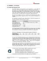
PROFIBUS ist ein durchgängiges, offenes, digitales Kommunikationssystem mit 
breitem Anwendungsbereich vor allem in der Fertigungs- 

und 

Prozessautomatisierung. PROFIBUS ist für schnelle, zeitkritische und für komplexe 
Kommunikationsaufgaben geeignet. 
 
Die Kommunikation


von PROFIBUS ist in den internationalen Normen IEC 61158 und 

IEC 61784 verankert. Die  Anwendungs-  und Engineeringaspekte sind in Richtlinien 
der PROFIBUS Nutzerorganisation festgelegt. Damit werden die 
Anwenderforderungen nach Herstellerunabhängigkeit und Offenheit erfüllt und die 
Kommunikation untereinander von Geräten verschiedener Hersteller ohne 
Anpassungen an den Geräten garantiert. 
 
Für Encoder wurde von der PROFIBUS Nutzerorganisation ein spezielles Profil 
verabschiedet. Das Profil beschreibt die Ankopplung von Dreh-, Winkel-  und Linear-
Encodern mit Singleturn-  oder Multiturn-Auflösung an DP. Zwei Geräteklassen 
definieren Basisfunktionen und Zusatzfunktionen, wie z. B. Skalierung, 
Alarmbehandlung und Diagnose. 
Die Mess-Systeme unterstützen neben denen im Profil definierten Geräte-Klassen 1 
und 2, noch zusätzliche TR-spezifische Funktionen. 
 
Eine Druckschrift des Encoder-Profils (Bestell-Nr.: 3.062) und weiterführende 
Informationen zum PROFIBUS ist bei der Geschäftsstelle der PROFIBUS-
Nutzerorganisation erhältlich: 


PROFIBUS Nutzerorganisation e.V., 

Haid-und-Neu-Str. 7, 
D-76131 Karlsruhe, 

http://www.profibus.com/


Tel.:  ++ 49 (0) 721 / 96 58 590 
Fax:  ++ 49 (0) 721 / 96 58 589 
e-mail: 

mailto:[email protected]


3.1.1 Kommunikationsprotokoll DP 

 
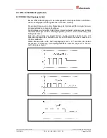
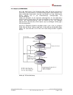
Die Mess-Systeme unterstützen das Kommunikationsprotokoll 

DP

, welches für einen 

schnellen Datenaustausch in der Feldebene konzipiert ist. Die Grundfunktionalität wird 
durch die Leistungsstufe 

V0

  festgelegt. Dazu gehören der zyklische Datenaustausch 

sowie die stations-, modul- und kanalspezifische Diagnose. 


Содержание COK-65

Страница 1: ...e _Installation _Inbetriebnahme _Konfiguration Parametrierung _St rungsbeseitigung Diagnosem glichkeiten _Additional safety instructions _Installation _Commissioning _Configuration Parameterization _T...

Страница 2: ...Ver nderung bedarf der schriftlichen Genehmigung durch den Hersteller Zuwiderhandlungen verpflichten zu Schadenersatz nderungsvorbehalt Jegliche nderungen die dem technischen Fortschritt dienen vorbe...

Страница 3: ...nschluss Hinweise 12 4 2 PROFIBUS Schnittstelle 13 4 2 1 RS485 bertragungstechnik 13 4 2 2 Bus Terminierung 14 4 2 3 Bus Adressierung 14 4 3 SSI Schnittstelle optional 15 4 3 1 RS422 bertragungstechni...

Страница 4: ...3 13 Short diagnostics 16 byte Kurze Diagnose 16 Byte 37 6 3 14 Limit switch lower and upper limit Endschalter unterer oberer Grenzw 37 6 3 15 Rpm multiplier Geschwindigkeit 1 n U min 37 6 4 Presetju...

Страница 5: ...mbH 2016 All Rights Reserved 10 31 2018 TR ECE BA DGB 0131 02 Page 5 of 103 nderungs Index nderung Datum Index Erstausgabe 12 12 16 00 LED Verhalten angepasst 24 02 17 01 LED Verhalten angepasst Hinwe...

Страница 6: ...g etc dar Das Benutzerhandbuch kann kundenspezifisch im Lieferumfang enthalten sein oder kann auch separat angefordert werden 1 1 Geltungsbereich Dieses Benutzerhandbuch gilt ausschlie lich f r folgen...

Страница 7: ...ess System mit optischer Abtastung 15 Bit Aufl sung Ausf hrung mit Sackloch COK Absolut Mess System mit optischer Abtastung 15 Bit Aufl sung Ausf hrung mit Kupplung DDLM Direct Data Link Mapper Schnit...

Страница 8: ...onen bzw Merkmale und Anwendungstipps des verwendeten Produkts 2 2 Erg nzende Hinweise zur bestimmungsgem en Verwendung Das Mess System ist ausgelegt f r den Betrieb an PROFIBUS DP Netzwerken nach den...

Страница 9: ...stems griffbereit aufbewahrt werden Das mit T tigkeiten am Mess System beauftragte Personal muss vor Arbeits beginn die Montageanleitung insbesondere das Kapitel Grundlegende Sicherheitshinweise und d...

Страница 10: ...tzerorganisation ein spezielles Profil verabschiedet Das Profil beschreibt die Ankopplung von Dreh Winkel und Linear Encodern mit Singleturn oder Multiturn Aufl sung an DP Zwei Ger teklassen definiere...

Страница 11: ...schelanfang synchronisiert wird ist es nicht notwendig einschrittige Codes wie z B Graycode zu verwenden Die Datensignale Daten und Daten werden mit Kabelsendern RS422 gesendet Zum Schutz gegen Besch...

Страница 12: ...as Mess System zus tzliche Schnittstellen z B eine SSI Schnittstelle externe Eing nge wie z B der Preset unterst tzt wird deshalb durch die ger tespezifische Steckerbelegung definiert Der Anschluss ka...

Страница 13: ...rd vom Mess System automatisch erkannt Sie wird bei der Inbetriebnahme des Systems einheitlich f r alle Ger te am Bus ausgew hlt Reichweite in Abh ngigkeit der bertragungsgeschwindigkeit f r Kabeltyp...

Страница 14: ...Teil nehmer im PROFIBUS Segment ist der Bus durch die Terminierungsschalter ON abzuschlie en In diesem Zustand wird der weiterf hrende PROFIBUS nicht abgekoppelt ON OFF ON OFF 4 2 3 Bus Adressierung...

Страница 15: ...sdifferenz zwischen zwei korrespondierenden Leitungen bertragen Der Empf nger wertet lediglich die Differenz zwischen beiden Leitungen aus so dass Gleichtakt St rungen auf der bertragungsleitung nicht...

Страница 16: ...0 Leitungsl nge m ca 12 5 ca 25 ca 50 ca 100 ca 200 ca 400 ca 500 Um eine hohe St rfestigkeit des Systems gegen elektromagnetische St rstrahlungen zu erzielen muss eine geschirmte Datenleitung verwend...

Страница 17: ...Taktsignals von Low auf High 2 wird das h chstwertige Bit MSB der Ger teinformation an den seriellen Datenausgang gelegt Mit jeder weiteren steigenden Flanke wird das n chst niederwertigere Bit an de...

Страница 18: ...aubung Variante A Pos 1 berwurfmutter Pos 2 Dichteinsatz Pos 3 Kontakth lse Pos 5 Einschraubstutzen 1 Schirmumflechtung Schirmfolie auf Ma X zur ckschneiden 2 berwurfmutter 1 und Dichteinsatz Kontakth...

Страница 19: ...auf das Kabel aufschieben 3 Die Schirmumflechtung Schirmfolie um ca 90 umbiegen 4 Klemmeinsatz 2 bis an die Schirmumflechtung Schirmfolie schieben und das Geflecht um den Klemmeinsatz 2 zur ckst lpen...

Страница 20: ...S_ www tr electronic de f TR ECE ID MUL 0007 TR0DAAAB GS_ www tr electronic de f TR ECE ID MUL 0013 Wird eine Messl nge 25 Bit ben tigt muss die GSD Datei TR0DAAAB GS_ benutzt werden Es k nnen nur die...

Страница 21: ...ng m ssen der Ger tetyp die Format und L ngeninformationen sowie die Anzahl der Ein und Ausg nge bereinstimmen Der Benutzer erh lt dadurch einen zuverl ssigen Schutz gegen Parametrierungsfehler Konnte...

Страница 22: ...US 1 Hz 10 Hz Bus Fail BF rot Bus Status STAT gr n Ursache Versorgung fehlt Hardwarefehler Parametrier oder Konfigurationsfehler Presetwert1 2 bzw Endschalter au erhalb Bereich falsche GSD Datei Speic...

Страница 23: ...che Oberfl chen zur Verf gung Die Bit bzw Byte Lage wird dabei im Hintergrund automatisch gemanagt Das Konfigurationsbeispiel Seite 39 verdeutlicht dies noch mal Konfiguration Die Festlegung der E A D...

Страница 24: ...Meldemodus Kurze Diagnose Messl nge in Schritten Umdrehungen Z hler Umdrehungen Nenner Code SSI Schnittstelle Datenbits SSI Schnittstelle Code PROFIBUS Schnittstelle Preset Endschalter 32 Bit IN 32 Bi...

Страница 25: ...t sequence Z hlrichtung 6 2 2 PNO Class 1 32 Bit resolution Kennung 0xD1 Das Mess System verwendet nur 2 Eingangsworte die ber den Bus konsistent bertragen werden Eingangsdoppelwort ED x Datenbyte 3 D...

Страница 26: ...agnose ein ausschalten Scaling function Skalierungsfunktion ein ausschalten Measuring units per revolution Schritte pro Umdrehung Total measuring range units Messl nge in Schritten 6 2 4 PNO Class 2 3...

Страница 27: ...Count sequence Z hlrichtung Commissioning diagnostics Diagnose Meldemodus ein ausschalten Commissioning function Inbetriebnahmefunktion Short diagnostics 16 byte Kurze Diagnose Total measuring range u...

Страница 28: ...nktion Short diagnostics 16 byte Kurze Diagnose Total measuring range units Messl nge in Schritten Revolutions numerator Umdrehungen Z hler Revolutions denominator Umdrehungen Nenner SSI code Ausgabec...

Страница 29: ...Klasse 1 Funktionen aktiv er skaliert den Positionswert nicht und er ist nicht justierbar Auswahl Default No Klasse 2 Funktionen ausgeschaltet Yes Klasse 2 eingeschaltet X 6 3 3 Commissioning diagnos...

Страница 30: ...s System bei einer Umdrehung der Mess System Welle ausgibt Untergrenze 1 Schritt Umdrehung Obergrenze 8192 Schritte pro Umdrehung Max Wert siehe Typenschild Default 4096 6 3 5 2 Total measuring range...

Страница 31: ...ie neu errechnete Messl nge in Schritten kann ber die erweiterte Diagnoseinformation f r CLASS 2 ausgelesen werden und ist immer kleiner als die vorgegebene Messl nge Es kann daher vorkommen dass die...

Страница 32: ...ufl sung des Mess Systems ver ndert werden Das Mess System unterst tzt die Getriebefunktion f r Rundachsen Dies bedeutet dass die Anzahl Schritte pro Umdrehung und der Quotient von Umdrehungen Z hler...

Страница 33: ...glich kann die entsprechende Kommanzahl m glicherweise nur ann hernd dargestellt werden Die sich ergebende kleine Ungenauigkeit wird bei echten Rundachsenanwendungen Endlos Anwendungen in eine Richtu...

Страница 34: ...erfassende Mechanik in Endlage bringen Den mechanisch zur ckgelegten Weg in mm vermessen Istposition des Mess Systems an der angeschlossenen Steuerung ablesen Annahme zur ckgelegter Weg 2000 mm Mess S...

Страница 35: ...f r die optionale SSI Schnittstelle fest Auswahl Default Gray Mess System liefert Gray Code X Binary Mess System liefert Bin r Code Shifted Gray Mess System liefert gekappten Gray Code 6 3 8 SSI data...

Страница 36: ...renze 0 Obergrenze Programmierte Gesamtmessl nge in Schritten 1 Default 0 6 3 11 Preset value 2 2 Presetwert Dieser Parameter legt fest auf welchen Positionswert das Mess System mit der steigenden Fla...

Страница 37: ...bnahmefunktion dem Master ber ein Bit mitteilen ob sich der Istwert innerhalb der Grenzen befindet Hierbei gilt Endschalterbit 0 wenn unterer Grenzwert Istwert oberer Grenzwert Endschalterbit 1 wenn I...

Страница 38: ...yte 3 Datenbyte 2 Datenbyte 1 Datenbyte 0 LSB MSB Ausgangsbyte x 0 Ausgangsbyte x 1 Ausgangsbyte x 2 Ausgangsbyte x 3 P Eing nge Der in den Datenbytes 0 3 bertragene Presetjustagewert wird mit der ste...

Страница 39: ...1 F r das Konfigurationsbeispiel wird vorausgesetzt dass die Hardwarekonfiguration bereits vorgenommen wurde Als CPU wird die CPU315 2 DP mit integrierter PROFIBUS Schnittstelle verwendet Dateinamen...

Страница 40: ...TR ELECTRONIC Der Eintrag der GSD Datei lautet TR ZE65 ZH80 DP Unter diesem Eintrag reihen sich die einzelnen Konfigurationsm glichkeiten an PNO Class 1 16 Bit siehe Seite 25 PNO Class 1 32 Bit siehe...

Страница 41: ...served 10 31 2018 TR ECE BA DGB 0131 02 Page 41 of 103 Mess System an das Mastersystem Drag Drop anbinden Mit Anbindung des Mess Systems an das Mastersystem k nnen die Netzeinstellungen vorgenommen we...

Страница 42: ...Printed in the Federal Republic of Germany Page 42 of 103 TR ECE BA DGB 0131 02 10 31 2018 Gew nschte Konfiguration aus dem Katalog auf den Steckplatz bertragen Drag Drop Das Mess System Symbol muss...

Страница 43: ...Endschalter m ssen sich innerhalb der programmierten Gesamtmessl nge in Schritten 1 befinden berpr fen ob die zum Mess System zugeh rige Ger te Stammdaten Datei installiert bzw konfiguriert wurde Vers...

Страница 44: ...ersichtsdiagnose als gest rt gemeldet kann der Host weitere Daten vom Master anfordern Slavediagnose die dann eine detailliertere Auswertung ber die Gr nde der St rung zulassen Die so gewonnenen Anzei...

Страница 45: ...ete Konfigurationskennung en wurde n vom Slave abgelehnt Bit 1 Station_Not_Ready Slave ist nicht zum Austausch zyklischer Daten bereit Bit 0 Station_Non_Existent Der Slave wurde projektiert ist aber a...

Страница 46: ...erforderlich dass bei gleichzeitigem Zugriff mehrerer Master deren Konfigurations und Parametrierinformation exakt bereinstimmt 7 2 1 5 Herstellerkennung Normdiagnose Byte 5 6 In die Bytes tr gt der S...

Страница 47: ...ebs Status 1 2 TR Byte 10 Encodertyp 1 2 TR Byte 11 14 Encoderaufl sung in Schritten pro Umdrehung rotatorisch Encoderaufl sung in Mess Schritten Linear 1 2 TR Byte 15 16 Anzahl aufl sbare Umdrehungen...

Страница 48: ...ncoder rotatorisch 01 Multiturn Absolut Encoder rotatorisch weitere Codes siehe Encoderprofil 7 2 2 4 Singleturn Aufl sung Erweiterte Diagnose Byte 11 14 ber die Diagnosebytes kann die hardwareseitige...

Страница 49: ...cht Kontrollreserve Nicht erreicht Erreicht Bit 3 CPU Watchdog Status OK Reset ausgef hrt Bit 4 Betriebszeitwarnung Nein Ja Bit 5 15 Batterieladung OK Zu niedrig 7 2 2 9 Unterst tzte Warnungen Erweite...

Страница 50: ...ung klein zu halten wird ein Diagnosetelegramm mit dem neuesten Z hlerstand gesendet aber nur nach jeder Parametrierung oder wenn ein Fehler gemeldet werden muss jedoch nicht wenn alles in Ordnung ist...

Страница 51: ...on ist nur bei eingeschalteter Commissioning Diagnostic Funktion gew hrleistet 7 3 Sonstige St rungen St rung Ursache Abhilfe Mess Systemspr nge starke Vibrationen Vibrationen Schl ge und St e z B an...

Страница 52: ...St rungsbeseitigung und Diagnosem glichkeiten TR Electronic GmbH 2016 All Rights Reserved Printed in the Federal Republic of Germany Page 52 of 103 TR ECE BA DGB 0131 02 10 31 2018...

Страница 53: ...Printed in the Federal Republic of Germany TR Electronic GmbH 2016 All Rights Reserved 10 31 2018 TR ECE BA DGB 0131 02 Page 53 of 103 User Manual CO_ 65 PROFIBUS DP ZE_ 65 replacement...

Страница 54: ...e the written content of the manufacturer Violations shall be subject to claims for damages Subject to modifications The right to make any changes in the interest of technical progress is reserved Doc...

Страница 55: ...2 PROFIBUS interface 65 4 2 1 RS485 Data transmission technology 65 4 2 2 Bus termination 66 4 2 3 Bus address 66 4 3 SSI interface optional 67 4 3 1 RS422 Data transmission technology 67 4 3 2 Cable...

Страница 56: ...ptional SSI interface 90 6 6 Configuration example SIMATIC Manager V5 3 91 7 Troubleshooting and diagnosis options 95 7 1 Optical displays LEDs 95 7 2 Use of the PROFIBUS diagnosis 96 7 2 1 Standard d...

Страница 57: ...GmbH 2016 All Rights Reserved 10 31 2018 TR ECE BA DGB 0131 02 Page 57 of 103 Revision index Revision Date Index First release 12 12 16 00 LED behavior edited 02 24 17 01 LED behavior edited Informat...

Страница 58: ...etc The User Manual may be included in the customer s specific delivery package or it may be requested separately 1 1 Applicability This User Manual applies exclusively to the following measuring sys...

Страница 59: ...asuring system with optical scanning unit 15 bit resolution Blind Shaft COK Absolute measuring system with optical scanning unit 15 bit resolution Integrated Claw Coupling DDLM Direct Data Link Mapper...

Страница 60: ...e product used 2 2 Additional instructions for proper use The measuring system is designed for operation with PROFIBUS DP networks according to the European standards EN 50170 and EN 50254 up to max 1...

Страница 61: ...of operation of the measuring system Prior to commencing work personnel working with the measuring system must have read and understood the assembly instructions in particular the chapter Basic safet...

Страница 62: ...Organization has implemented a special profile for encoders The profile describes the connection of rotary angular and linear encoders with single turn or multi turn resolution to the DP Two device cl...

Страница 63: ...d by the start of the sequence it is not necessary to use single step codes such as Gray code The data signals Data and Data are transmitted by means of cable transmitters RS422 The clock signals Cloc...

Страница 64: ...ue Whether the measuring system supports additional interfaces e g a SSI interface external inputs such as the Preset is therefore defined by the device specific pin assignment The connection can be m...

Страница 65: ...y recognized by the measuring system It is selected for all devices on the bus at the time of commissioning the system The range is dependent on the transmission speed for cable type A Baud rate kbits...

Страница 66: ...ng system is the last slave in the PROFIBUS segment the bus is to be terminated with the two termination switches ON In this state the subsequent PROFIBUS isn t decoupled ON OFF ON OFF 4 2 3 Bus addre...

Страница 67: ...ansmitted without mass reference as a voltage difference between two corresponding lines The receiver evaluates only the difference between the two lines Therefore common mode interferences on the tra...

Страница 68: ...810 750 570 360 220 120 100 Line length m approx 12 5 approx 25 approx 50 approx 100 approx 200 approx 400 approx 500 A shielded data cable must be used to achieve high electromagnetic interference s...

Страница 69: ...st change of the clock pulse from low to high 2 the most significant bit MSB of the device information will be output to the serial data output With each following rising edge of the clock pulse the n...

Страница 70: ...ng is fitted on the inside Cable gland assembly variant A Pos 1 Nut Pos 2 Seal Pos 3 Contact bush Pos 5 Screw socket 1 Cut shield braid shield foil back to dimension X 2 Slide the nut 1 and seal conta...

Страница 71: ...clamping ring 2 over the cable 3 Bend the shield braining shield foil to approx 90 4 Push clamping ring 2 up to the shield braid shield foil and wrap the braiding back around the clamping ring 2 such...

Страница 72: ...Download TR06AAAB GS_ www tr electronic de f TR ECE ID MUL 0007 TR0DAAAB GS_ www tr electronic de f TR ECE ID MUL 0013 If a measuring length of 25 bit is required the GSD file TR0DAAAB GS_ is to be u...

Страница 73: ...ration The device type the format and length information as well as the number of inputs and outputs must agree in this check The user is therefore reliably protected against parameterization errors I...

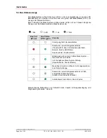
Страница 74: ...Hz Bus Fail BF red Bus Status STAT green Cause No supply voltage hardware error Parameter or configuration error Preset value1 2 or limit switch out of range wrong GSD file Memory error position error...

Страница 75: ...e for this purpose Here the bit and byte positions are automatically managed in the background The configuration example on page 91 illustrates this again Configuration The definition of the I O lengt...

Страница 76: ...missioning diagnostics Short Diagnostics Total measuring range Revolutions numerator Revolutions denominator Code SSI Interface Data bits SSI Interface Code PROFIBUS Interface Preset Limit switch 32 b...

Страница 77: ...t sequence 6 2 2 PNO Class 1 32 bit resolution identifier 0xD1 The measuring system uses two input words only which are consistently transferred via the bus Double input word ID x Data byte 3 Data byt...

Страница 78: ...ass 2 functionality Commissioning diagnostics Scaling function Measuring units per revolution Total measuring range units 6 2 4 PNO Class 2 32 bit resolution identifier 0xF1 The measuring system uses...

Страница 79: ...0 Input byte x 1 Input byte x 2 Input byte x 3 Double output word for preset adjustment OD x Data byte 3 Data byte 2 Data byte 1 Data byte 0 LSB MSB Output byte x 0 Output byte x 1 Output byte x 2 Ou...

Страница 80: ...ta byte 0 LSB MSB Output byte x 0 Output byte x 1 Output byte x 2 Output byte x 3 P P Preset adjustment Relevant parameter data Count sequence Commissioning diagnostics Commissioning function Short di...

Страница 81: ...m only performs Class 1 functions does not scale the position value and is not adjustable Selection Default No Class 2 functions deactivated Yes Class 2 activated X 6 3 3 Commissioning diagnostics Def...

Страница 82: ...ing system outputs for one revolution of the measuring system shaft Lower limit 1 step revolution Upper limit 8192 steps per revolution Max value see nameplate Default 4096 6 3 5 2 Total measuring ran...

Страница 83: ...calculated total measuring range can be read from the extended diagnosis information for CLASS 2 and is always shorter than the specified measurement length It may therefore occur that the total numb...

Страница 84: ...be used to change the physical resolution of the measuring system The measuring system supports the gearbox function for round axes This means that the Steps per revolution and the quotient of Revolut...

Страница 85: ...reduce these accordingly If this is not possible it may only be possible to represent the decimal number affected approximately The resulting minor inaccuracy accumulates for real round axis applicat...

Страница 86: ...hanics to be measured to the end position Measure the mechanical distance covered in mm Read off the actual value of the measuring system from the controller connected Assumed Distance covered 2000 mm...

Страница 87: ...output code for the optional SSI interface Selection Default Gray measuring system outputs gray code X Binary measuring system outputs binary code Shifted Gray measuring system outputs shifted gray c...

Страница 88: ...measuring length in increments Lower limit 0 Upper limit Programmed total measuring length in increments 1 Default 0 6 3 11 Preset value 2 Defines the position value to which the measuring system is...

Страница 89: ...m can inform the master via a bit whether the actual value is within the limits It is valid Limit switch bit 0 if lower limit actual value upper limit Limit switch bit 1 if actual value lower limit or...

Страница 90: ...byte 0 LSB MSB Output byte x 0 Output byte x 1 Output byte x 2 Output byte x 3 P Inputs Data byte 3 Data byte 2 Data byte 1 Data byte 0 LSB MSB Input byte x 0 Input byte x 1 Input byte x 2 Input byte...

Страница 91: ...MATIC Manager V5 3 For the configuration example it is assumed that the hardware configuration has already taken place The CPU315 2 DP with integrated PROFIBUS interface is used as CPU File names and...

Страница 92: ...S DP Additional Field Devices Encoder TR ELECTRONIC The entry for the GSD file is TR ZE65 ZH80 DP The sequence of the respective configuration options is given in this entry PNO Class 1 16 bit see pag...

Страница 93: ...2016 All Rights Reserved 10 31 2018 TR ECE BA DGB 0131 02 Page 93 of 103 Connect measuring system to the master system drag drop Once the measuring system is connected to the master system the network...

Страница 94: ...d Printed in the Federal Republic of Germany Page 94 of 103 TR ECE BA DGB 0131 02 10 31 2018 Transfer the required configuration from the catalogue to the slot drag drop The measuring system symbol mu...

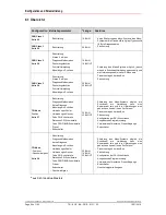
Страница 95: ...et or limit switches must be within the programmed measuring system range in steps 1 Check whether the device master file associated with the measuring system has been installed or configured Switch s...

Страница 96: ...ummary diagnosis the host can request further data from the master slave diagnostics which then allow a more detailed evaluation of the causes The indications thus obtained may either have been genera...

Страница 97: ...lt The configuration identifier s sent by the master was were rejected by the slave Bit 1 Station_Not_Ready Slave is not ready to exchange cyclical data Bit 0 Station_Non_Existent The slave has been c...

Страница 98: ...figuration and parameterization information must coincide exactly in order to ensure correct operation of the Profibus 7 2 1 5 Manufacturer s identifier Standard diagnosis byte 5 6 In this bytes the s...

Страница 99: ...tatus 1 2 TR Byte 10 Encoder type 1 2 TR Byte 11 14 Encoder resolution in increments per revolution rotary Encoder resolution in measuring increments linear 1 2 TR Byte 15 16 Number of resolvable revo...

Страница 100: ...e turn absolute encoder rotary 01 Multi turn absolute encoder rotary See encoder profile for other codes 7 2 2 4 Single turn resolution Extended diagnosis byte 11 14 Via this bytes the hardware single...

Страница 101: ...ontrol reserve light Not reached Reached Bit 3 CPU watchdog status OK Reset performed Bit 4 Operating time warning No Yes Bit 5 15 Battery charge OK Too low 7 2 2 9 Supported warnings Extended diagnos...

Страница 102: ...agnostic telegram is sent with the latest counter state after every parameter setting or if an error must be reported If everything is correct and only the counter has changed no new diagnosis telegra...

Страница 103: ...the error via the PROFIBUS in this way This function is only guaranteed provided the Commissioning diagnostics function is activated 7 3 Other faults Fault Cause Remedy measuring system step changes...

Отзывы: