User's Manual l MBLS1028A UM 0100 l © 2020, TQ-Systems GmbH
Page 22
4.3.8
SD card
The SD card socket is directly connected via a 4-bit data interface to the uSDHC controller of the TQMLS1028A.
The uSDHC controller in the TQMLS1028A supports UHS-I mode.
The USDHC1 signals are supplied by EVDD (10 kΩ PU to 1.8 V or 3.3 V).
The I/O voltage is switched by the TQMLS1028A signal SDHC1_VSEL.
The SD card supply is fixed at 3.3V. The signal lines have PUs to 3.3 V. This ensures that the pull-up voltage is at the correct level
after automatic switching to UHS-I mode. All data lines are ESD protected.
It is possible to boot from SD card.
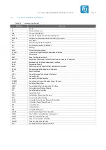
Figure 18: Block diagram SD card
Table 18:
Pinout SD card, X16
Pin
Signal
Remark
1
SDHC1_DATA2_R
10 kΩ PU to 3.3 V + ESD protection
2
SDHC1_DATA3_R
10 kΩ PU to 3.3 V + ESD protection
3
SDHC1_CMD_R
10 kΩ PU to 3.3 V + ESD protection
4
VCC3V3
Optional: 1.8 V or 3.3 V
5
SDHC1_CLK
ESD protection
6
DGND
–
7
SDHC1_DATA0_R
10 kΩ PU to 3.3 V + ESD protection
8
SDHC1_DATA1_R
10 kΩ PU to 3.3 V + ESD protection
SW1
SDHC1_CD#
10 kΩ PU to 1.8 V + ESD protection
SW2
DGND
–
M1 … M4
SHIELD
Shield
Note: SD card supply voltage
SD cards always start with 3.3 V I/O voltage after power-up.
For the modes with 1.8 V I/O voltage they are switched by software.
When rebooting or resetting the MBLS1028A, the SD card remains at the last used I/O voltage
because it does not have a separate reset signal. The SDHC controller, on the other hand, returns to
3.3 V I/O voltage. Therefore, the supplied BSP is limited to the 3.3 V modes.


