A09687
Upward
Cam Lobe
Clearance
A87966
A88503
Upward
Notch
Cam Lobe
Intake
Manifold
Side
A62959
SST (B)
SST (A)
A09615
Magnetic
Finger
14
−
18
−
ENGINE MECHANICAL
PARTIAL ENGINE ASSY (1CD
−
FTV)(From September,
2003)
1CD
−
FTV ENGINE REPAIR MANUAL (RM1046E)
44.
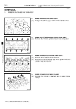
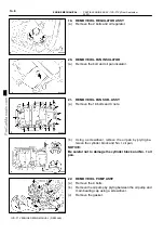
INSPECT VALVE CLEARANCE
(a)
Turn the crankshaft so that the cam lobe located over the
inspecting valve faces upward.
(b)
Using a feeler gauge, measure the clearance between
the valve lifter and camshaft.
(c)
Measure the clearance at 16 places.
(d)
Record the out
−
of
−
specification valve clearance mea-
surements. They will be used later to select an adjusting
shim to replace.
Valve clearance (Cold) :
Intake
0.20 to 0.30 mm (0.008 to 0.012 in.)
Exhaust
0.35 to 0.45 mm (0.014 to 0.018 in.)
45.
ADJUST VALVE CLEARANCE
(a)
Remove the adjusting shim.
(1)
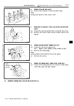
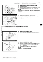
Turn the crankshaft so that the cam lobe located
over the adjusting valve faces upward.
(2)
Position the notch of the valve lifter toward the in-
take manifold side.
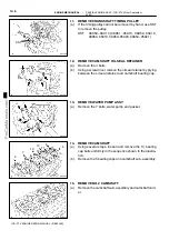
(3)
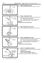
Using SST (A), press down the valve lifter, then
place SST (B) between the camshaft and valve lift-
er. Remove SST (A).
SST
09248
−
55050 (09248
−
05510, 09248
−
05520)
HINT:
Use SST (B) marked with ”11”.
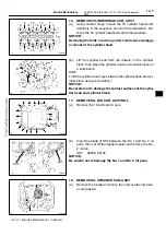
(4)
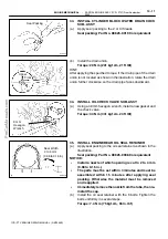
Remove the adjusting shim using a small screwdriv-
er and magnetic finger.

