background image

4-20

Toshiba

Disassembly and Reassembly

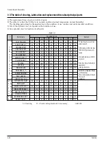
1-3 The table of clearing, Lubrication and replacement time about principal parts

1) The replacement time of parts is not life of parts.
2) The table 1-1 is that the VCR Set is in normal condition (normal temperature, normal humidity).

The checking period may be changed owing to the condition of use, runtime and environmental conditions.

3) Life of the Cylinder Ass’y is depend on the condition of use.
4) See exploded view for location of each parts.

<Table 1-1>

: Cleaning          O : Check and replacement in necessary          


: Add Oil

T

A

PE 

P

A

T

H

S
Y
S

T
E

M

D

R

I

V

I

N

G

*

Parts Name

Checking Period

Remark

500

1000

1500

2000

2500

3000

3500

4000

4500

5000

POST TENSION

SLANT POST S, T

#8 GUIDE SHAFT

CAPSTAN SHAFT

#9 GUIDE POST

#3 GUIDE POST

GUIDE ROLLER S, T

O

O

O

O

O

O

O

CYLINDER ASS’Y

O

O

O

O

O

O

O

O

O

FE HEAD

O

O

O

O

O

O

O

ACE HEAD

O

O

O

O

O

O

O

O

O

PINCH ROLLER

O

O

O

O

O

O

O

O

O

POST REEL S, T

SLEEVE TENSION

POST CENTER

LEVER IDLE BOSS (2Point)

CAPSTAN MOTOR PULLEY

O

O

O

O

O

BELT PULLEY

O

O

O

O

O

O

O

HOLDER CLUTCH ASS’Y

O

O

O

O

O

O

O

O

O

GEAR CENTER ASS’Y

O

O

O

O

O

O

O

O

O

GEAR IDLE (2Point)

O

O

O

O

O

O

O

O

O

LOADING MOTOR

O

O

O

O

O

O

O

O

O

BAND BRAKE ASS’Y

O

O

O

O

O

O

O

O

O

BRAKE T ASS’Y

O

O

O

O

O

O

O

O

O

S
Y
S

T
E

M

- Periodic time of applying oil (Apply

oil after cleaning)

- The excessive applying oil may be

the cause of 
malfunction.

- To clean the parts, use patch and

alcohol (solvent).

- After cleaning, use the video tape

after alcohol is gone away com-
pletely.

- We recommend to use oil [EP-50]

or solvent.

- One or two drops of oil should be

applied after 
cleaning with alcohol.

B
R

A

K

E

S

Y

S

T

E

M

Содержание W-422

Страница 1: ...SERVICE MANUAL FILE NO 120 200191 VIDEO CASSETTE RECORDER W 422 NOV 2001 W 422 11 27 01 3 23 PM Page 1 ...

Страница 2: ...S 1 Precautions 2 Reference Information 3 Product Specifications 4 Disassembly and Reassembly 5 Alignment and Adjustment 6 Exploded View 7 Replacement Parts List 8 Block Diagram 9 PCB Diagrams 10 Schematic Diagrams ...

Страница 3: ...eed 0 5 milliamp Reverse the power plug prongs in the AC outlet and repeat the test 6 X ray Limits The picture tube is designed to prohibit X ray emissions To ensure continued X ray protection replace the picture tube only with one that is the same type as the original Fig 1 1 AC Leakage Test 7 Antenna Cold Check With the unit s AC plug disconnected from the AC source connect an electrical jumper ...

Страница 4: ...ument s ground lead to the instrument chassis ground before connecting the positive lead always remove the instrument s ground lead last 17 Observe the original lead dress especially near the following areas Antenna wiring sharp edges and especially the AC and high voltage power supplies Always inspect for pinched out of place or frayed wiring Do not change the spacing between components and the p...

Страница 5: ...A SELECT Number buttons VCR TV 20 15 18 20 20 15 15 20 21 25 23 27 28 25 TV VCR 21 Multifunctional indicator VCR indicator Cassette indicator Timer recording indicator VCR Display VCR TIMER Hi Fi Hi Fi indicator For W 522 only 8 Front Panel model W 522 INTRODUCTION Identification of Controls See the page in for details This manual shows the names of buttons in italics POWER REC Front Panel model W...

Страница 6: ...light source such as direct sunlight or illumination especially high frequency lighting when using the remote control Be careful not to spill water on the remote control or to place it on anything wet and avoid sharp impacts How to Use the Remote Control This section explains how to get ready for remote control operation PREPARATION 10 Rear Panel model W 522 INTRODUCTION L R CH selector 3 4 LINE O...

Страница 7: ...acks You will need to press I SELECT so that the VCR display shows L Cable box Incoming cable Cable box OUT IN Only for model W 522 12 Antenna VCR TV Connection 1 Disconnect the antenna cable from your TV and connect it to the RF IN terminal on the VCR 2 Connect the RF OUT terminal to the TV AUDIO VIDEO Connections The AUDIO VIDEO jacks are also available to connect your TV When connected your TV ...

Страница 8: ...VCR POWER I SELECT SP SLP DISPLAY TV VOL COUNTER PROG CANCEL REMAIN RESET COUNT EJECT CM SKIP 1 2 3 6 5 4 100 9 8 7 0 A SELECT ENTER STOP F F REW PLAY VCR POWER REW FF PLAY STOP PROG ENTER 3 Select the language using PLAY or STOP and press PROG The screen turns to the MENU screen E n D PROG ENTER Page 23 Page 29 Page 24 To change the language move down here and set to the desired one For W 522 onl...

Страница 9: ...TOP 1 Set SUMMER TIME Daylight Saving Time DST start Daylight saving time begins on the first Sunday in April Because the clock automatically changes from 2 00 AM to 3 00 AM forward one hour DST end Daylight saving time ends on the last Sunday in October The VCR clock automatically changes from 2 00 AM to 1 00 AM back one hour remember that any part of a scheduled Timer Recording that falls betwee...

Страница 10: ...5 46 47 48 49 50 51 R S T U V W AA BB CC DD EE FF GG HH II JJ KK LL MM NN OO 52 53 54 55 56 57 58 59 60 61 62 63 64 65 66 67 68 69 70 71 52 53 54 55 56 57 58 59 60 61 62 63 64 65 66 67 68 69 PP QQ RR SS TT UU VV WW XX YY ZZ AAA BBB 65 66 67 68 69 70 71 93 94 95 96 97 98 99 100 101 102 103 121 122 123 124 125 93 94 A 5 A 4 A 3 A 2 A 1 100 101 102 103 121 122 123 124 125 3 Enter a channel number of ...

Страница 11: ... during playback The VCR will automatically search forward for 30 seconds to a maximum of 3 minutes six presses and then resume normal playback 20 Adjusting the tracking When playback starts the VCR automatically adjusts the tracking for clear pictures and sound Digital Auto Tracking If the VCR cannot locate the best possible tracking point hold down one of CH TRK to adjust the tracking manually N...

Страница 12: ...work on non recorded portions on the tape When the tape is ejected or the VCR is turned off the display changes to clock If the tape rewinds back over 00 00 appears in the VCR display The displayed time of the linear time counter is only an approximation Linear time counter Tape remaining time R Clock E n D PROG SAP SET on off COU n TER MEM on off LA n GUAGE E n G FRA ESP TAPE LE n GTH 120 160 180...

Страница 13: ...g in progress press POWER on the VCR VCR VCR VCR REC TIMER S VCR L TIMER VCR RECORDING Recording a TV Program This section explains the basic recording operation Preparation Select the video channel 3 or 4 or video input mode on the TV REC TIMER SLOW PAUSE STILL REC TIMER TV VCR POWER I SELECT SP SLP DISPLAY TV VOL COUNTER PROG CANCEL REMAIN RESET COUNT EJECT CM SKIP F F REW PLAY ENTER A SELECT 1 ...

Страница 14: ... selected and the tape length is not sufficient to record the program to the end the program cannot be recorded to the end The picture will be distorted when playing the part where the recording tape speed is switched from SP to SLP with the Auto Speed Select feature Hi Fi STEREO SAP L TIMER Timer Program Recording continued 8 25 9 25 7 25 WKLYSU MO FR WKLYSA REC TIMER P M 26 Timer Programming Pro...

Страница 15: ...e VCR the output sound is monaural Desired sound SAP sound Stereo sound L R indicators in the On Screen display R right is on Both R right and L left are on Sound output SAP HIFI Sound RECORDING SLOW PAUSE STILL REC TIMER TV VCR POWER I SELECT SP SLP DISPLAY TV VOL COUNTER PROG CANCEL REMAIN RESET COUNT EJECT CM SKIP 1 2 3 6 5 4 100 9 8 7 0 ENTER A SELECT STOP F F REW PLAY 1 A SELECT DISPLAY 2 28 ...

Страница 16: ...Adjust the tracking manually page 20 The timer recording function does not work There is an error in programming Reset the timer recording program page 28 There is no cassette in the VCR Load a cassette with the safety tab attached page 19 The cassette does not have the safety tab Use another cassette with a safety tab or cover the hole with adhesive tape page 19 The timer indicator is not display...

Страница 17: ... the front of the VCR page 11 An obstacle may be in the way of the operation Remove the obstacle The operating mode of the remote control is not set correctly Press VCR or TV depending on the equipment you want to operate pages 15 30 The cassette is ejected immediately after it is loaded The cassette was inserted with the label side not paralleling the compartment Reload it carefully page 19 The c...

Страница 18: ...Reference Information 2 14 Toshiba 2 2 1 IC301 LA71201M 2 2 IC Blocks ...

Страница 19: ...Reference Information Toshiba 2 15 2 2 2 IC601 MN101D02D ...

Страница 20: ...nditions 120V AC 60Hz 16W 360 x 94 x 252 mm W H D 3 0 kg VHF Channels 2 13 UHF Channels 14 69 CATV Channels A7 A1 A CCC 66 125 UHF VHF 75ohm F type connector Standard NTSC Recording VHS format SP SLP Playback VHS format SP LP SLP Video cassette with VHS mark SLP 11 1 mm s SP 33 4 mm s SLP 480 minutes SP 160 minutes When T 160 video cassette is used Within approx 60 s When T 120 video cassette is u...

Страница 21: ...4 1 1 Cabinet Top Removal Œ REMOVE 2 SCREWS Lift up the Cabinet Top in the direction of arrow by releasing the Hook Fig 4 1 Cabinet Top Removal 4 1 2 Ass y Front Panel Removal Fig 4 2 Ass y Front Panel Removal Œ RELEASE 4 HOOKS RELEASE 3 HOOKS TOP VIEW BOTTOM VIEW ...

Страница 22: ...bly and Reassembly 4 1 4 Chassis Removal Fig 4 4 Chassis Removal Œ 2 SCREWS BRACKET FRAME ASS Y DECK ASS Y MAIN PCB RELEASE HOOK RELEASE HOOK ˇ 4 SCREWS ˆ FLAT CABLE Ø FLAT CABLE FLAT CABLE ASSEMBLY POINT ALIGN TWO ARROWS ...

Страница 23: ...d Reassembly Toshiba 4 3 4 2 Deck Parts Locations 4 2 1 Top View Œ ˇ ˆ Ø Fig 4 5 Top parts Location 1 Œ GEAR FL CAM MOTOR LOADING ASS Y ˇ LEVER FL ARM ASS Y HOLDER FL CASSETTE ASS Y ˆ LEVER FL DOOR Ø SLIDER FL DRIVE ...

Страница 24: ... ˇ ˆ Fig 4 6 Top Parts Location 2 Œ FE HEAD CYLINDER ASS Y ˇ ACE HEAD ASS Y LEVER UNIT PINCH ASS Y ˆ LEVER 9 GUIDE ASS Y Ø LEVER TENSION ASS Y BAND BRAKE ASS Y DISK S REEL LEVER S BRAKE ASS Y GEAR IDLE Ô LEVER IDLE LEVER T BRAKE ASS Y Ò DISK T REEL ...

Страница 25: ...hiba 4 5 1 1 2 Bottom View Œ ˇ ˆ Ø Fig 4 7 Bottom Parts Location Œ GEAR JOINT 1 GEAR JOINT 2 ˇ BRACKET GEAR MOTOR CAPSTAN ASS Y ˆ LEVER T LOAD ASS Y Ø GEAR LOADING DRIVE LEVER S LOAD ASS Y HOLDER CLUTCH ASS Y BELT PULLEY SLIDER CAM ...

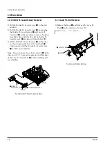
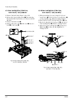
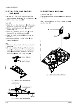
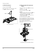
Страница 26: ...me to release hooking from Main Base until the Boss A of Holder FL Cassette Ass y Œ is taken out from the Rail B 3 Lift the Holder FL Cassette Ass y Œ in this time you have to grasp the Lever FL Cassette R Continuously until the Holder FL Cassette Ass y Œ is taken out completely Note Be sure to insert Lever FL Cassette R in the direction of A to prevent separation and breakage of the Lever FL Cass...

Страница 27: ...der FL Drive Gear FL Cam Removal 1 Pull the Slider FL Drive Œ to the front direction 2 Remove the Slider FL Drive Œ in the direction of arrow Refer to Fig 4 10 3 Remove the Gear FL cam Note When reinstalling be sure to reassemble Slider FL drive Œ after you insert the Boss of Lever FL ARM R in Groove of Slider Fl drive Œ Assembly Align the Gear FL Cam Œ with the Gear worm wheel Post as shown drawi...

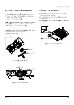
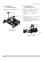
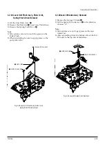
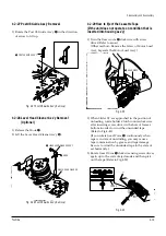
Страница 28: ...of Cable Flat Œ from Connector Waffer 2 Remove the Loading Motor connecting part of Cable Flat Œ from Connector Waffer ˇ 3 Rotate the Damper Capstan in the direction of arrow A and remove it toward B 4 Pull the Cable Flat Œ in the direction of arrow C to remove ˇ CONNECTOR WAFER DAMPER CAPSTAN CONNECTOR WAFER CYLINDER CONNECTING PART LOADING MOTOR CONNECTING PART Œ CABLE FLAT C A B Fig 4 14 Cable ...

Страница 29: ...oint 2 as shown Fig 4 17 Refer to Timing point1 2 Confirm the Timing Point 2 of the Gear Joint 2 and Slider Cam ˇ Œ SCREW BRAKET GEAR GEAR JOINT 1 ˇ GEAR JOINT 2 Fig 4 16 Bracket Gear Gear Joint 1 2 Removal Œ GEAR JOINT1 GEAR JOINT2 ˇ SLIDER CAM TIMING POINT 1 TIMING POINT 2 Fig 4 17 Gear Joint 1 2 Assembly 1 2 7 Motor Loading Ass y Removal 1 Remove the screw Œ 2 Remove the Motor Loading Ass y MOT...

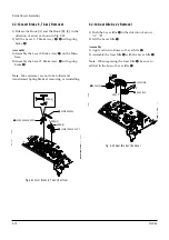
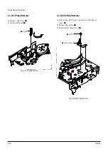
Страница 30: ...o Timing Point 3 LEVER LOAD S Œ LEVER LOAD T LEVER LOAD S LEVER LOAD T PIN A PIN C PIN B PIN D ˇ SLIDER CAM TIMING POINT 2 TIMING POINT 1 TIMING POINT 3 Fig 4 19 Gear Loading Drive Slider Cam Lever Load S T Ass y Assembly 1 2 9 Gear Loading Drive Slider Cam Lever Load S T Ass y Removal 1 Remove the Belt Pulley Refer to Fig 4 35 2 Remove the Gear Loading Drive Œ after releasing Hook A in the direct...

Страница 31: ...ure to apply Grease on the post 2 Take care not to touch stain on the felt side and not to be folder and broken Band brake Ass y 3 After Lever Tension Ass y seated Rotate stopper of Main Base to the Mark B Œ SPRING TENTION LEVER STOPPER MARK B A LEVER TENTION ASS Y ˇ BAND BRAKE ASS Y Fig 4 21 Lever Tension Ass y Band Brake Ass y Removal 1 2 11 Lever Pinch Drive Lever Tension Drive Removal 1 Remove...

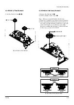
Страница 32: ...IDLE A HOOK C B Fig 4 23 Gear Idle Ass y Removal 1 2 13 Lever Brake S T Ass y Removal 1 Release the Hook A and the Hook B C in the direction of arrow as shown in Fig 4 22 2 Lift the Lever S T Brake Ass y Œ with spring brake ˇ Assembly 1 Assembly the Lever S Brake Ass y Œ on the Main Base 2 Assembly the Lever T Brake Ass y with spring brake ˇ Note Take extreme care not to be folded and transformed ...

Страница 33: ... Clutch Ass y down with exces sive force Just insert Holder Clutch Ass y into post center with dead force and Rotate it smoothly Be sure to confirm that spring is in the slit of Gear Center Ass y as shown in detail B Œ DISK S REEL DISK T REEL Œ WASHER SLIT HOLDER CLUTCH ASS Y DETAIL A BAD SPRING GOOD BAD SPRING GOOD DETAIL B Fig 4 24 Disk S T Reel Removal Fig 4 25 Holder Clutch Ass y Removal 1 2 1...

Страница 34: ...ar holes on Main Base as shown in Fig 4 27 2 Lift the Lever Up Down Ass y Œ about 35 Refer to Fig 4 27 3 Insert Ring of the Gear Center Ass y in the Guide of the Lever Up Down Ass y Œ 4 Insert the Gear Center Ass y in the post on Main Base 5 Push down the Lever Up Down Ass y Œ for locking of the Hook Note 1 Take care not to separate and sentence does not mark sense 2 Be sure to confirm that Ring o...

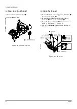
Страница 35: ...ply grease on the post pinch roller ˇ SPRING PINCH DRIVE Œ LEVER UNIT PINCH ASS Y PLATE JOINT Fig 4 29 Lever Unit Pinch Ass y Plate Joint Spring Pinch Drive Removal 1 2 20 Lever 9 Guide Ass y Removal 1 Remove the Spring 9 Guide Œ 2 Lift the Spring 9 Guide Ass y in the direction of arrow A Note 1 Take extreme care not to get grease on the tape Guide Post 2 After reinstalling check the bottom side o...

Страница 36: ...d Removal 1 Pull out the FPC from connector of ACE Head Ass y 2 Remove the screw Œ 3 Lift the ACE Head Ass y Œ SCREW HEAD ACE ASS Y Fig 4 32 ACE Head Removal 1 2 21 FE Head Removal 1 Remove the screw Œ 2 Lift the FE Head Œ FE HEAD Fig 4 31 FE Head Removal ...

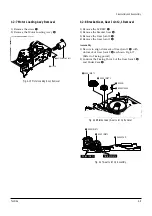
Страница 37: ...t the Cylinder Ass y ˇ Assembly 1 Match the 3 holes in the bottom of Cylinder ass y ˇ to the 3 holes of Main Base as attending not to drop or knock the Cylinder ass y ˇ 2 Tighten the 1 Screw Œ 3 Match the Plate Ground Deck to the Hole of Base Main 4 Tighten the other 2 Screws Œ Note 1 Take care not to touch the Cylinder Ass y ˇ and the tape guide post at reinstalling 2 When reinstalling Don t push...

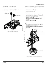
Страница 38: ... shown detail drawing 3 Assemble the Damper Capstan Œ Note After tightening screws check if there is gap between the head of screws and the top side of Main Base There should have no gap between the head of screws and the top side of Main Base After reinstalling adjusting the tape transport system again B C A 3 SCREWS ˇ MOTOR CAPSTAN ASS Y Œ DAMPER CAPSTAN Fig 4 36 Damper Capstan Motor Capstan Ass...

Страница 39: ...ed tape Refer to Fig 4 40 If you rotate Gear Worm Œ continuously when tape is in state of unwinding you may cause a tape contamination by grease and tape damage Be sure to wind the unwinded tape in the state of set horizently 3 Rotate Gear Worm Œ clockwise using screw driver again up to the state of eject mode and then pick out the tape Refer to Fig 4 39 FRAME 1 2 27 Post 8 Guide Ass y Removal 1 R...

Страница 40: ...DE SHAFT CAPSTAN SHAFT 9 GUIDE POST 3 GUIDE POST GUIDE ROLLER S T O O O O O O O CYLINDER ASS Y O O O O O O O O O FE HEAD O O O O O O O ACE HEAD O O O O O O O O O PINCH ROLLER O O O O O O O O O POST REEL S T SLEEVE TENSION POST CENTER LEVER IDLE BOSS 2Point CAPSTAN MOTOR PULLEY O O O O O BELT PULLEY O O O O O O O HOLDER CLUTCH ASS Y O O O O O O O O O GEAR CENTER ASS Y O O O O O O O O O GEAR IDLE 2P...

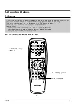
Страница 41: ...cessory is available for all adjustments 5 How to adjustment Monmently short circuit the test point on Main PCB with pincets to set the adjustment mode If the corresponding adjustment button is pressed the adjustment is preformed automatically If the adjustment is completed be sure to turn the power off 5 1 1 Location of adjustment button of remote control Fig 5 1 X Point Tracking Center Adjustmen...

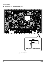
Страница 42: ...5 2 Toshiba Alignment and Adjustment 5 1 2 Test point location for adjustment mode setting Fig 5 2 Main PCB Top View Short Circuit for a second and release ...

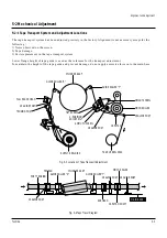
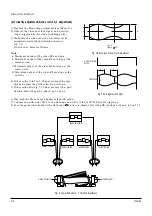
Страница 43: ...for the transport adjustment To maintain the height of the tape guide and prevent damage do not apply excessive force onto the main base Fig 5 3 Location of Tape Transport Adjustment Fig 5 4 Tape Travel Diagram CYLINDER ASS Y TAKE UP REEL DISK 8 GUIDE POST 9 GUIDE POST SUPPLY REEL DISK CAPSTAN PINCH ROLLER GUIDE ROLLER T GUIDE ROLLER S FULL ERASE HEAD 3 GUIDE POST TENSION POST HEIGHT SCREW TILT SC...

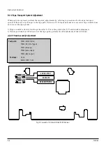
Страница 44: ...oes not occur at the tape guides 1 If tape wrinkle is observed at the guide roller S T turn the guide roller S T until wrinkle disappears 2 If the tape wrinkle is still observed at the tape guide perform the tilt adjustment of the ACE head 1 ACE Head Assembly Adjustment Test point TP601 Control Pulse TP602 H D S W Trigger TP301 Envelope TP302 Audio output TP303 Video output Test tape ST N1 BLANK T...

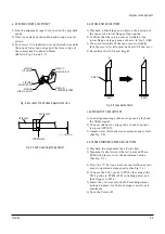
Страница 45: ...ower flange of tape guide as shown in Fig 5 8 B 3 If a curl or wrinkle of the tape occurrs slightly turn the screw A tilt adjust on the ACE head ass y 4 Reconfirm the ACE head height Fig 5 8 Tape Guide Check c AUDIO AZIMUTH ADJUSTMENT 1 Load alignment tape Mono scope and playback the 7KHz signal 2 Connect channel 1 scope probe to audio output test point TP302 3 Adjust screw B to achieve maximum au...

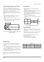
Страница 46: ...deo RF envelope at the exit side 4 If the section A in Fig 5 10 does not meet the spec ification adjust the guide roller S up or down 5 If the section B in Fig 5 10 does not meet the speci fication adjust the guide roller T up or down Fig 5 9 Envelope Waveform Adjustment a a b c d c b d a 63 b c d Fig 5 10 Adjustment Points A B A B H D SWITCHING PULSE ENVELOPE 6 Play back the Mono Scope alignment ...

Страница 47: ...using with T 120 E 120 The video envelope should meet the specification as shown in Fig 5 13 In SP mode A should equal B If the head gap is wide upper cylinder should be checked A B Fig 5 13 Envelope Output and Output Level 5 Tape Wrinkle Check 1 Run the T 160 E 180 tape in the playback FPS RPS and Pause modes and observe tape wrinkle at each guide 2 If excessive tape wrinkle is observed perform t...

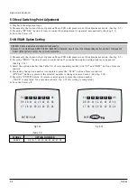
Страница 48: ...button of remote control 4 If selecting the option number is completed press the PLAY button of remote control If PLAY button is pressed the selected number is changes reversed color See Fig 5 14 5 Press the ENTER button of remote control again to store the option number SAVE is displayed for a second as shown Fig 5 15 this setting is completed 6 Turn the Power off 1 NVRAM Option is adjusted at pr...

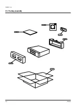
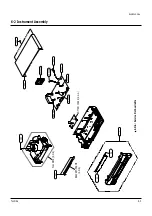
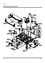
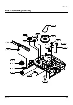
Страница 49: ...Toshiba 6 1 6 Exploded View 6 1 Packing Assembly 6 2 Instrument Assembly 6 3 Mechanical Parts Top Side 6 4 Mechanical Parts Bottom Side 6 2 6 3 6 4 6 5 ...

Страница 50: ...Exploded View 6 2 Toshiba 6 1 Packing Assembly Y101 A702 A701 Y102 UT01 A702 ...

Страница 51: ...Exploded View Toshiba 6 3 6 2 Instrument Assembly S N A Service Not Available 21 22 1 FULL DECK S N A BRACKET FRAME S N A 157 153 TM401B 101 601 155 200 CN303B S602A S601A LD601A BOTTOM COVER S N A ...

Страница 52: ...echanical Parts Top Side G001 G555 B475 B561 G510 G480 K546 G680 G681 B410 B440 B448 B452 G546 G560 G060 G520 G527 K188 K182 K110 K240 K248 K350 K330 K140 K340 G070 K470 B474 B473 K250 K530 K490 G530 G420 G450 K502 OPTIONAL OPTIONAL ...

Страница 53: ...Exploded View Toshiba 6 5 6 4 Mechanical Parts Bottom Side G542 B462 B560 B501 B484 B488 B500 B456 B458 B464 B468 K222 K200 K225 K221 B478 B570 B460 B489 ...

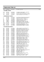
Страница 54: ...74 BY730244 AC61 30180A PLATE JOINT X 9 SECC20 20 T0 8 B475 BY731053 AC47 00003A DAMPER CAPSTAN SCORPIO2 POM NATUAL B478 BY730747 AC66 00016A LEVER TENSION DRIVE TS 10 SECC E20 20 1 B484 BY730755 AC66 00030A GEAR LOADING DR ASS Y TS 10 POM SWPB B488 BY730753 AC66 00023A LEVER S LOADING TS 10 POM NAT B489 BY730751 AC66 00021A LINK LOADING S TS 10 SECC E20 20 0 8 B500 BY730754 AC66 00024A LEVER T LO...

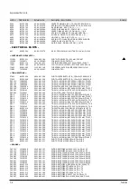
Страница 55: ...2 TR SMALL SIGNAL KTC3203 Y NPN 400MW T0 9 Q601 BY530014 0504 000119 TR DIGITAL KSR1004 NPN 300MW 47K 47K TO Q702 70795818 0501 000290 TR SMALL SIGNAL KSA643 Y PNP 500mW TO 92 Q703 70795818 0501 000290 TR SMALL SIGNAL KSA643 Y PNP 500mW TO 92 Q704 70795818 0501 000290 TR SMALL SIGNAL KSA643 Y PNP 500mW TO 92 Q705 70795818 0501 000290 TR SMALL SIGNAL KSA643 Y PNP 500mW TO 92 Q706 70795136 0501 0003...

Страница 56: ...0uH 10 4 2x9 8mm L308 70795862 2702 000166 INDUCTOR RADIAL 47uH 5 6x6 4mm L601 BY330019 3301 000297 CORE FERRITE BEAD AA 3 6x1 2x5 7mm 1400 L602 BY330009 2701 000002 INDUCTOR AXIAL 100uH 10 4 2x9 8mm L603 BY330019 3301 000297 CORE FERRITE BEAD AA 3 6x1 2x5 7mm 1400 L802 BY330019 3301 000297 CORE FERRITE BEAD AA 3 6x1 2x5 7mm 1400 LD601 BY430016 0601 000517 LED IR RECTANGULA 4x6 0mm 75mW 6V 950 CAP...

Страница 57: ...8 2nF 10 50V X7R TP 2012 C352 70796281 2203 000260 C CERAMIC CHIP 10nF 10 50V X7R TP 2012 C353 BY130206 2401 001254 C AL 4 7uF 20 35V GP TP 4x7 5 C354 70795976 2203 000938 C CERAMIC CHIP 0 47nF 5 50V NP0 TP 2012 C355 BY130209 2301 000110 C FILM PEF 1 8nF 5 100V TP 7x3 0x6 5mm C356 BY130282 2401 003107 C AL 47uF 20 16V GP TP 5x7 5 C357 BY130375 2301 000174 C FILM PEF 15nF 5 100V TP 7 2x4 0x7 5mm C3...

Страница 58: ...IDE 0 68ohm 5 2W AE TP 6x16mm R1SR07 70795040 2001 000734 R CARBON 4 7KOHM 5 1 8W AA TP 1 8X3 2M R1SS01 BY230027 2003 000994 R METAL OXIDE S 33Kohm 5 2W AF TP 3 9x R1SS02 BY230027 2003 000994 R METAL OXIDE S 33Kohm 5 2W AF TP 3 9x R1SS04 70795005 2001 000429 R CARBON 1KOHM 5 1 8W AA TP 1 8X3 2MM R1SS05 70795640 2004 000869 R METAL 3Kohm 1 1 8W AA TP 1 8x3 2mm R1SS06 70795638 2004 000459 R METAL 2 ...

Страница 59: ... 8X3 2M R641 70795006 2001 000290 R CARBON 10KOHM 5 1 8W AA TP 1 8X3 2MM R643 70795516 2007 000300 R CHIP 10KOHM 5 1 10W DA TP 2012 R644 70795516 2007 000300 R CHIP 10KOHM 5 1 10W DA TP 2012 R645 70795516 2007 000300 R CHIP 10KOHM 5 1 10W DA TP 2012 R646 70795539 2007 000981 R CHIP 5 6KOHM 5 1 10W DA TP 2012 R647 70795531 2007 000766 R CHIP 330OHM 5 1 10W DA TP 2012 R648 70795531 2007 000766 R CHI...

Страница 60: ...T701 BY634672 AC07 00029A LED DISPLAY BCD 9007E BRIGHT W 527 VR82 F1SD01 70795420 3601 001122 FUSE CARTRIDGE 250V 1 6A FAST ACTING GLA FC1SS1 BY634083 3602 000103 FUSE CLIP 10mohm FC1SS2 BY634083 3602 000103 FUSE CLIP 10mohm GP601 BY730731 AC63 00043A SHIELD CASE GROUND PCB SV 643F STPE T0 3 JK801 BY634002 AC37 20001H JACK RCA DPAM 4P MONO PI3 3 PT1SD1 BY330067 AC26 00002B TRANS SWITCHING EE2621 U...

Страница 61: ...438B ALEXANDRA ROAD BLOCK B 06 01 ALEXANDRA TECHNOPARK SINGAPORE 119968 TOSHIBA VIDEO PRODUCTS PTE LTD W 422 11 27 01 3 23 PM Page 2 ...

Отзывы: