background image

4. BIOS SETUP


EO18-12017 


4.3 BIOS Setup Screen Configuration and Default Setting 

4- 13 

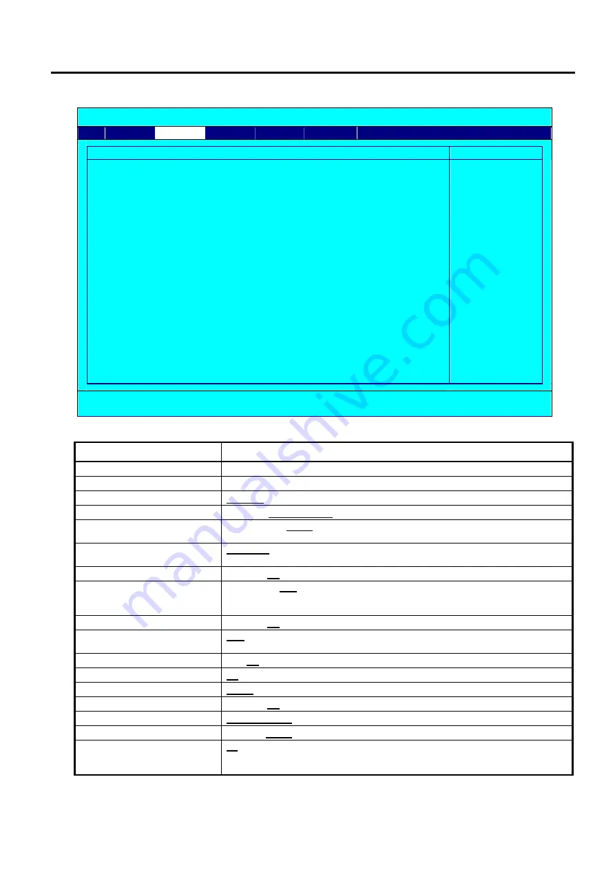
(6)  DRAM Clock/Drive Control Menu 

Phoenix - AwardBIOS CMOS Setup Utility 


Advanced 


DRAM Clock/Drive Control 

Item Help 


×


×


×


×


×


×


×


× 


Current FSB Frequency 
Current DRAM Frequency


DRAM Clock 
DRAM Timing 

SDRAM CAS Latency [DDR/DDR2]

Bank Interleave 
Precharge to Active(Trp) 
Active to Precharge(Tras) 
Active to CMD(Trcd) 
REF to ACT/REF (Trfc) 
ACT(0) to ACT(1) (TRRD)


Read to Precharge (Trtp) 
Write to Read CMD (Twtr) 
Write Recovery Time (Twr) 
DRAM Command Rate 
RDSAIT mode 

RDSAIT selection 

100MHz 
266MHz 

[By SPD] 
[Auto By SPD] 

2.5/ 4 
Disabled 
4T 
07T 
4T 
21T 
3T


[2T] 
[1T/2T] 
[4T] 
[2T Command] 
[Auto] 

03 

 Menu Level  


↑↓→←

:Move    Enter:Select    +/-/PU/PD:Value    F10:Save    ESC:Exit    F1:General Help 

         F5:Previous Values        F6:Optimized Defaults 

*: X mark above shows its readings don’t have any meaning and can’t be changed when it’s linked to other items. 


Setup Item 

Selective Item (Default setting is indicated by boldface.) 

Current FSB Frequency 

Auto-setup (not changeable).


Current DRAM Frequency 

Auto-setup (not changeable). 

DRAM Clock 

By SPD

 / 200 MHz / 266 MHz 

DRAM Timing 

Manual /

 Auto By SPD 

SDRAM CAS Latency 

[DDR/DDR2] 

1.5/ 2 / 2/ 3 / 

2.5/ 4

 / 3/ 5  

(Selectable only when DRAM Timing is set to Manual) 

Bank Interleave 

Disabled

 / 2 Bank / 4 Bank / 8 Bank  

(Selectable only when DRAM Timing is set to Manual)


Precharge to Active(Trp) 

2T / 3T / 

4T

 / 5T (Selectable only when DRAM Timing is set to Manual) 

Active to Precharge(Tras) 

05T / 06T / 

07T

 / 08T / 09T / 10T / 11T / 12T / 13T / 14T / 15T / 16T / 17T / 

18T / 19T / 20T 

(Selectable only when DRAM Timing is set to Manual) 

Active to CMD(Trcd) 

2T / 3T / 

4T

 / 5T (Selectable only when DRAM Timing is set to Manual) 

REF to ACT/REF (Trfc) 

21T 

08T - 71T (1T Step) (Selectable only when DRAM Timing is set to Manual)

ACT(0) to ACT(1) (TRRD) 

2T / 

3T

 / 4T / 5T (Selectable only when DRAM Timing is set to Manual) 

Read to Precharge (Trtp) 

2T

 / 3T 

Write to Read CMD (Twtr) 

1T/2T

 / 2T/3T 

Write Recovery Time (Twr) 

2T / 3T / 

4T

 / 5T 

DRAM Command Rate 

2T Command

 / 1T Command 

RDSAIT mode 

Manual /

 Auto


RDSAIT selection 

03 

Min=0000 Max=003F Key in a HEX number :  

(Selectable only when RDSAIT mode is set to Manual) 

Содержание ST-B10 SERIES

Страница 1: ...PRINTED IN JAPAN TOSHIBA POS Terminal ST B10 SERIES Document No EO18 12017 Original Mar 2010 Revised Maintenance Manual ...

Страница 2: ...n NOTES 1 Manual instructions must be followed when installing option kits or adding cables to avoid system failures and to insure proper performance and operation 2 Failure to follow manual instructions or any unauthorized modification substitution or change to this product will void the limited product warranty ...

Страница 3: ...3 Replacing the PS Unit 3 8 3 4 Replacing the Fan Motor 3 11 3 5 Replacing the Panel Card 3 15 4 BIOS SETUP 4 1 4 1 General 4 1 4 2 Basic Operation and Keys Used 4 1 4 3 BIOS Setup Screen Configuration and Default Setting 4 6 4 4 Notes and Restrictions 4 28 Appendix 1 BIOS Error Message List 4 31 5 DIAGNOSTIC TEST OPERATION 5 1 5 1 Outline 5 1 5 2 Serviceman Diagnostic Test Program Setup Procedure...

Страница 4: ...y have in this manual Copyright 2010 by TOSHIBA TEC CORPORATION All Rights Reserved 570 Ohito Izunokuni shi Shizuoka ken JAPAN NOTE Pictures in this manual show that body colour may differ from that of the original 8 APPENDIX 8 1 8 1 Serial Interface COM1 to COM6 8 1 8 2 VGA Connector 8 2 8 3 DRW1 Cash Drawer 24V Type 8 2 8 4 LAN 8 2 8 5 USB 8 3 8 6 PS 2 Keyboard Mouse 8 3 8 7 LINEOUT 8 3 8 8 LVDS...

Страница 5: ...Procedure 1 1 1 UNPACKING 1 1 Procedure 1 Open the carton 2 Take out the POS terminal and then remove the pads 3 Place the POS terminal on a level surface ST B10 OUTER CAB LEFT ST B10 OUTER CAB RIGHT ST B10 MACHINE ST B10 CARTON ...

Страница 6: ...t side of the POS terminal so as not to block the ventilating slits and the fan Since heat is built up inside the POS terminal during operation the ventilating slits and the fan are provided to vent the internal air 2 When installing the display unit on the top cover the following conditions must be satisfied Display unit weights 12kg or less The base of the display unit has no protrusions that mi...

Страница 7: ...lithium battery on the ENGINE PC board This section describes procedures to install optional equipments into the POS terminal 2 1 Removing Attaching the Top Cover Removing the Top Cover 1 Loose these 2 of plastic thumbscrew of the top cover 2 Press the top cover from the left side and right side and then slide it down Plastic thumbscrew Turn it anticlock w ise to loose the plastic thumbscrew 1 Pre...

Страница 8: ... 2 Note when attaching the Top Cover 1 Place the top cover on B10 PLT BTM then fully slide the top cover frontward so that the ten hooks of the top cover the six hooks on both sides and the four on the front side fit into the base frame Hook of both side on top cover Hook of front side on top cover ...

Страница 9: ... FOR OPTIONAL EQUIPMENT EO18 12017 2 1 Removing Attaching the Top Cover 2 3 1 Placed the top cover on the B10 PLT BTM 2 Align the top cover to this line 3 Press the top cover at left and right side and then slide it frontw ard ...

Страница 10: ...OS Optional Device Document No EO21 12001 POS OPTIONAL DEVICE BASIC SPECIFICATION 2 Please use TOSHIBA TEC approved HDDs Failure to do this may cause an error Installation procedure for the HDD is shown below Required Parts The following part is required to install an HDD HDD Unit with B10 Catch HDD NOTE This is an accessory part of the POS terminal Installation Procedure 1 Open the front cover Un...

Страница 11: ...e Hard Disk Drive HDD 2 5 2 Put in HDD into the slot on the Front side of B10 machine 4 Connect the HDD by pushing it frontward until hear the sound of TICK Put the HDD with B10 HDD Catch into this slot at the front side of machine Push it frontward until hear the sound of TICK ...

Страница 12: ...R OPTIONAL EQUIPMENT EO18 12017 2 2 Installing the Hard Disk Drive HDD 2 6 5 Turn these 2 pcs of plastic thumbscrews clockwise to lock B10 HDD Catch with HDD 6 Close the front cover of ST B10 machine Lock the plastic thumbscrews ...

Страница 13: ...careful not to short circuit the Lithium Battery on the ENGINE PC board 3 Be careful not to injure your fingers when replacing the main parts 3 1 Replacing the Main Board 1 Open B10 PLT TOP COV by loosing the plastic thumbscrew 2 Slide B10 PLT TOP COV out from B10 PLT BTM Loosen the thumbscrew 1 Press Top Cov in these 2 directions Press Top Cov in these 2 directions ...

Страница 14: ... 12017 3 1 Replacing the Main Board 3 2 3 Dismantle sata cable and power supply cable 4 Slide B10 PLT PCB TRAY out and take it out from B10 PLT BTM Dismantle Sata cable and power supply cable Slide B10 PLT PCB TRAY in this way out ...

Страница 15: ... REPLACEMENT EO18 12017 3 1 Replacing the Main Board 3 3 5 Unscrew 7 pcs of the screw Replace the main board with the new part in the reverse order of removal Take it out from B10 PLT BTM M3X6 PAN HEAD CUP FLG ZC ...

Страница 16: ...LVDS Display Card 3 4 3 2 Replacing the LVDS Display Card 1 Open B10 PLT TOP COV by loosing the plastic thumbscrew 2 Slide B10 PLT TOP COV out from B10 PLT BTM Loosen the thumbscrew 1 Press Top Cov in these 2 directions Press Top Cov in these 2 directions ...

Страница 17: ...17 3 2 Replacing the LVDS Display Card 3 5 3 Dismantle sata cable and power supply cable 4 Slide B10 PLT PCB TRAY out and take it out from B10 PLT BTM Dismantle Sata cable and power supply cable Slide B10 PLT PCB TRAY in this way out ...

Страница 18: ...3 MAIN UNIT REPLACEMENT EO18 12017 3 2 Replacing the LVDS Display Card 3 6 5 Unscrew 7 pcs of the screw from the main board Take it out from B10 PLT BTM M3X6 PAN HEAD CUP FLG ZC ...

Страница 19: ...IN UNIT REPLACEMENT EO18 12017 3 2 Replacing the LVDS Display Card 3 7 6 Unscrew 4 pcs of screws from LVDS Display card Replace it with the new part in the reverse order of removal M3X6 PAN HEAD CUP FLG ZC ...

Страница 20: ...acing the PS Unit 3 8 3 3 Replacing the PS Unit 1 Open B10 PLT TOP COV by loosing the plastic thumbscrew 2 Slide B10 PLT TOP COV out from B10 PLT BTM Loosen the thumbscrew 1 Press Top Cov in these 2 directions Press Top Cov in these 2 directions ...

Страница 21: ...8 12017 3 3 Replacing the PS Unit 3 9 3 Dismantle sata cable and power supply cable 4 Slide B10 PLT PCB TRAY out and take it out from B10 PLT BTM Dismantle Sata cable and power supply cable Slide B10 PLT PCB TRAY in this way out ...

Страница 22: ...it 3 10 5 Unscrew 5 pcs of screws from PS board and unplug the earth wire HDD power cable and fan cable from PS board Replace the PS unit with the new part in the reverse order of removal Take it out from B10 PLT BTM M3X6 PAN HEAD CUP FLG ZC Unplug these cable ...

Страница 23: ...ng the Fan Motor 3 11 3 4 Replacing the Fan Motor 1 Open B10 PLT TOP COV by loosing the plastic thumbscrew 2 Slide B10 PLT TOP COV out from B10 PLT BTM Loosen the thumbscrew 1 Press Top Cov in these 2 directions Press Top Cov in these 2 directions ...

Страница 24: ... 12017 3 4 Replacing the Fan Motor 3 12 3 Dismantle sata cable and power supply cable 4 Slide B10 PLT PCB TRAY out and take it out from B10 PLT BTM Dismantle Sata cable and power supply cable Slide B10 PLT PCB TRAY in this way out ...

Страница 25: ...3 MAIN UNIT REPLACEMENT EO18 12017 3 4 Replacing the Fan Motor 3 13 5 Unplug the fan cable from PS board Take it out from B10 PLT BTM Unplug this fan motor cable ...

Страница 26: ...nscrew 2 pcs of screw from B10 PLT FAN and 1 pc of screw from B10 PLT BTM 7 Unscrew again 2 pcs of screw from B10 PLT FAN and replace it with the new part in reverse order of removal M3X6 PAN HEAD CUP FLG ZC M5X10 PAN P TITE BF P P 5x10 3BC M5X10 PAN P TITE BF P P 5x10 3BC ...

Страница 27: ...g the Panel Card 3 15 3 5 Replacing the Panel Card 1 Open B10 PLT TOP COV by loosing the plastic thumbscrew 2 Slide B10 PLT TOP COV out from B10 PLT BTM Loosen the thumbscrew 1 Press Top Cov in these 2 directions Press Top Cov in these 2 directions ...

Страница 28: ...eplacing the Panel Card 3 16 3 Pull out B10 COV HDD in the following way 4 Unscrew and pull out B10 CATCH HDD 1 Slowly pull out the side of B10 COV HDD in this way 2 Pull out another side of B10 COV HDD out 1 Loosen thumbscrew 2 Pull out HDD ...

Страница 29: ...3 MAIN UNIT REPLACEMENT EO18 12017 3 5 Replacing the Panel Card 3 17 5 Unlatch B10 COV FRONT from B10 PLT BTM Unlatch these 3 latches Push the latch of B10 COV FRONT out from B10 PLT BTM ...

Страница 30: ...CEMENT EO18 12017 3 5 Replacing the Panel Card 3 18 6 Take out B10 COV FRONT from B10 PLT BTM 7 Unplug ST B10 PANEL FFC from main board Pull out the bottom latch from B10 PLT BTM Unplug ST B10 PANEL FFC from main board ...

Страница 31: ...3 MAIN UNIT REPLACEMENT EO18 12017 3 5 Replacing the Panel Card 3 19 8 Unscrew the Panel Card and replace it with the new part in reverse order of removal M3X6 PAN HEAD CUP FLG ZC ...

Страница 32: ... Phoenix Technologies LTD CN7_S10 Vx xx xx xx xxxx Main Processor VIA C7 1 50GHz 100x15 0 Memory Testing 457664K OK 64M shared memory DDR DIMM Speed 533 DDR DIMM Data Width 64 Bit Single Channel Detecting IDE Drives SATA HDD WDC800BEVS 22VAT0 11 01A11 SATA Press F2 to enter SETUP 01 14 2010 CN700 8237S 8A7L600KC 00 4 2 2 Table of the Function Keys The following are the keys usable on the BIOS setu...

Страница 33: ...ry Total Memory Main Menu SATA HDD0 SATA Auto Detection SATA Drive Access Mode Capacity Cylinder Head Precomp Landing Zone Sector 2 Advanced Menu Menu 1st line Menu 2nd line Menu 3rd line Menu 4th line First Boot Device Second Boot Device Boot Other Device USB Storage Function USB Mass Storage Device Boot Setting Boot Up Numlock Status Security Option APIC Mode Summary Screen Show CPU Feature Dela...

Страница 34: ...ure Size AGP 3 0 Mode AGP Driving Control AGP Driving Value AGP Fast Write AGP Master 1 WS Write AGP Master 1 WS Read AGP 3 0 Calibration Cycle VGA Share Memory Size Direct Frame Buffer Select Display Device Output Port Dithering Advanced Chipset Features CPU PCI Bus Control PCI Master 0 WS Write PCI Delay Transaction Vlink mode selection Vlink 8X Support DRDY Timing VIA OnChip PCI Device Azalia H...

Страница 35: ...port WDRT Run Stop WDRT Count Power management Setup Wakeup Event Detect PowerOn by PCI Card RTC Alarm Resume PnP PCI Configurations PNP OS Installed Reset Configuration Data Resources Controlled By PCI VGA Palette Snoop Assign IRQ For VGA Assign IRQ For USB PCI express relative items Maximum ASPM supported Maximum Payload Size Advanced Menu IRQ Resources IRQ 3 assigned to IRQ 4 assigned to IRQ 5 ...

Страница 36: ...lth Menu 1st line PC Health Current CPU Temperature Current System Temp Smart CPU Temperature CPU Range Value CPU Fan Speed Chassis Fan Speed VCC 5 VTR 5 V 12 V 5 Clk Voltage Menu Menu 1st line Clk Voltage Menu Auto Detect PCI Clk Spread Spectrum CPU Clock 6 Exit Menu Menu 1st line Exit Menu Save Exit Setup Exit Without Saving Load Setup Defaults ...

Страница 37: ...an 14 2010 11 48 52 WDC WD800BEVS 22VAT0 EGA VGA 640K 456704K 457728K Menu Level Change the day month year and century Move Enter Select PU PD Value F10 Save ESC Exit F1 General Help F5 Previous Values F6 Optimized Defaults Setup Item Selective Item Default setting is indicated by boldface Date Month Day Year MM DD YYYY MM 1 12 DD 1 31 YYYY 2000 2099 When the battery is dead 1 1 2000 is displayed ...

Страница 38: ...nu Level To audio detect the HDD s size head on this channel Move Enter Select PU PD Value F10 Save ESC Exit F1 General Help F5 Previous Values F6 Optimized Defaults Setup Item Selective Item Default setting is indicated by boldface SATA Auto Detection None SATA Drive None Auto Access Mode Large Auto Capacity Auto setup not changeable Cylinder Auto setup not changeable Head Auto setup not changeab...

Страница 39: ...res Integrated Peripherals Power Management Setup PnP PCI Configurations Menu Level Virus Protection Boot Sequence Move Enter Select PU PD Value F10 Save ESC Exit F1 General Help F5 Previous Values F6 Optimized Defaults Setup Item Selective Item Default setting is indicated by boldface Advanced BIOS Features to sub menu Advanced Chipset Features to sub menu Integrated Peripherals to sub menu Power...

Страница 40: ...U PD Value F10 Save ESC Exit F1 General Help F5 Previous Values F6 Optimized Defaults Setup Item Selective Item Default setting is indicated by boldface CPU Feature to sub menu Hard Disk Boot Priority to sub menu First Boot Device LS120 Hard Disk CDROM ZIP100 USB FDD USB ZIP USB CDROM Legacy LAN Disabled Second Boot Device LS120 Hard Disk CDROM ZIP100 USB FDD USB ZIP USB CDROM Legacy LAN Disabled ...

Страница 41: ...mized Defaults X mark above shows its readings don t have any meaning and can t be changed when it s linked to other items Setup Item Selective Item Default setting is indicated by boldface Delay Prior to Thermal 4 Min 8 Min 16 Min 32 Min Thermal Management Thermal Monitor 1 Thermal Monitor 2 Thermal Monitor Bus Ratio 8 X Selectable only when Thermal Management is set to Thermal Monitor 2 Thermal ...

Страница 42: ...isk Boot Priority Item Help 1 SATA HDD WDC WD800BEVS 22VAT0 2 Bootable Add in Cards Menu Level Use or to select a device then press to move it up or to move it down the list Press ESC to exit this menu Move Enter Select PU PD Value F10 Save ESC Exit F1 General Help F5 Previous Values F6 Optimized Defaults Select Hard Disk Boot Priority by using PageUp or PageDown Key ...

Страница 43: ...rol CPU PCI Bus Control Video RAM Cacheable Init Display First Disabled PCI Slot Menu Level Move Enter Select PU PD Value F10 Save ESC Exit F1 General Help F5 Previous Values F6 Optimized Defaults Setup Item Selective Item Default setting is indicated by boldface DRAM Clock Drive Control To sub menu AGP P2P Bridge Control To sub menu CPU PCI Bus Control To sub menu Video RAM Cacheable Disabled Ena...

Страница 44: ...boldface Current FSB Frequency Auto setup not changeable Current DRAM Frequency Auto setup not changeable DRAM Clock By SPD 200 MHz 266 MHz DRAM Timing Manual Auto By SPD SDRAM CAS Latency DDR DDR2 1 5 2 2 3 2 5 4 3 5 Selectable only when DRAM Timing is set to Manual Bank Interleave Disabled 2 Bank 4 Bank 8 Bank Selectable only when DRAM Timing is set to Manual Precharge to Active Trp 2T 3T 4T 5T ...

Страница 45: ...ve ESC Exit F1 General Help F5 Previous Values F6 Optimized Defaults X mark above shows its readings don t have any meaning and can t be changed when it s linked to other items Setup Item Selective Item Default setting is indicated by boldface AGP Aperture Size 32M 64M 128M 256M 512M 1G AGP3 0 Mode 8X 4X AGP Driving Control Auto Manual AGP Driving Value DA Min 0000 Max 00FF Key in a HEX number Sel...

Страница 46: ...ction VLink 8X Support DRDY_Timing Enabled Enabled By Auto Enabled Default Menu Level Move Enter Select PU PD Value F10 Save ESC Exit F1 General Help F5 Previous Values F6 Optimized Defaults Setup Item Selective Item Default setting is indicated by boldface PCI Master 0 WS Write Disabled Enabled PCI Delay Transaction Disabled Enabled VLink mode selection By Auto Mode 0 Mode 1 VLink 8X Support Disa...

Страница 47: ...ated Peripherals Item Help VIA OnChip PCI Device SuperIO Device USB Device Setting Press Enter Menu Level Move Enter Select PU PD Value F10 Save ESC Exit F1 General Help F5 Previous Values F6 Optimized Defaults Setup Item Selective Item Default setting is indicated by boldface VIA OnChip PCI Device To sub menu SuperIO Device To sub menu USB Device Setting To sub menu ...

Страница 48: ...PCI Device Item Help Azalia HAD Controller LAN Controller Lan Boot ROM Auto Enabled Disabled Menu Level Move Enter Select PU PD Value F10 Save ESC Exit F1 General Help F5 Previous Values F6 Optimized Defaults Setup Item Selective Item Default setting is indicated by boldface Azalia HAD Controller Disabled Auto LAN Controller Disabled Enabled Lan Boot ROM Disabled Enabled ...

Страница 49: ...IRQ5 Menu Level Move Enter Select PU PD Value F10 Save ESC Exit F1 General Help F5 Previous Values F6 Optimized Defaults X mark above shows its readings don t have any meaning and can t be changed when it s linked to other items Setup Item Selective Item Default setting is indicated by boldface Onboard Serial Port 1 Disabled 3F8 IRQ4 Onboard Serial Port 2 Disabled 2F8 IRQ3 Onboard Serial Port 3 Di...

Страница 50: ... Enabled Full Low Speed Enabled Enabled Menu Level Enable or Disable Universal Host Controller Interface for Universal Serial Bus Move Enter Select PU PD Value F10 Save ESC Exit F1 General Help F5 Previous Values F6 Optimized Defaults Setup Item Selective Item Default setting is indicated by boldface USB 1 0 Controller Disabled Enabled USB 2 0 Controller Disabled Enabled USB Operation Mode Full Lo...

Страница 51: ... and can t be changed when it s linked to other items Setup Item Selective Item Default setting is indicated by boldface ACPI function Enabled Auto setup not changeable ACPI Suspend Type S1 POS Auto setup not changeable Power Management Option User Define Min Saving Max Saving HDD Power Down Disable 1 Min 15 Min 1Min Step Suspend Mode Disable 1 Min 2 Min 4 Min 6 Min 8 Min 10 Min 20 Min 30 Min 40 M...

Страница 52: ...ty Advanced Wakeup Event Detect Item Help PowerOn by PCI Card RTC Alarm Resume Enabled Disabled Menu Level Move Enter Select PU PD Value F10 Save ESC Exit F1 General Help F5 Previous Values F6 Optimized Defaults Setup Item Selective Item Default setting is indicated by boldface PowerOn by PCI Card Disabled Enabled RTC Alarm Resume Disabled Enabled ...

Страница 53: ... if you are using a Plug and Play capable operating system Select No if you need the BIOS to configure non boot devices Move Enter Select PU PD Value F10 Save ESC Exit F1 General Help F5 Previous Values F6 Optimized Defaults Setup Item Selective Item Default setting is indicated by boldface PNP OS Installed No Yes Reset Configuration Data Disabled Enabled Resources Controlled By Auto ESCD Manual I...

Страница 54: ...h the original PC AT bus specification PCI ISA PnP for devices compliant with the Plug and Play standard whether designed for PCI or ISA bus architecture Move Enter Select PU PD Value F10 Save ESC Exit F1 General Help F5 Previous Values F6 Optimized Defaults Setup Item Selective Item Default setting is indicated by boldface IRQ 3 assigned to PCI Device Reserved IRQ 4 assigned to PCI Device Reserve...

Страница 55: ...ced Security PC Health Clk Voltage Exit Item Help Set Supervisor Password Set User Password Menu Level Change Set Disable password Move Enter Select PU PD Value F10 Save ESC Exit F1 General Help F5 Previous Values F6 Optimized Defaults Setup Item Selective Item Default setting is indicated by boldface Set Supervisor Password None Set User Password None ...

Страница 56: ...es F6 Optimized Defaults Setup Item Selective Item Default setting is indicated by boldface Current CPU Temperature Auto setup not changeable Current System Temp Auto setup not changeable Smart CPU Temperature Disabled 40 C 104 F 45 C 113 F 50 C 122 F 55 C 131 F 60 C 140 F 65 C 149 F 70 C158 F CPU Range Value 2 C 2 5 C 3 33 C 4 C 5 C 6 67 C 8 C 10 C 13 33 C 16 C 20 C 26 67 C 32 C 40 C 53 33 C 80 C...

Страница 57: ... Exit Item Help Auto Detect PCI Clk Spread Spectrum CPU Clock Enabled 0 20 100MHz Menu Level Move Enter Select PU PD Value F10 Save ESC Exit F1 General Help F5 Previous Values F6 Optimized Defaults Setup Item Selective Item Default setting is indicated by boldface Auto Detect PCI Clk Enabled Disabled Spread Spectrum Disabled 0 20 0 25 0 35 CPU Clock 100 Min 100 Max 132 Key in a DEC number ...

Страница 58: ...0 Save ESC Exit F1 General Help F5 Previous Values F6 Optimized Defaults Setup Item Selective Item Default setting is indicated by boldface Save Exit Setup Refer the following Save Exit Confirmation Message Exit Without Saving Refer the following Exit Confirmation Message Load Setup Defaults Refer the following Load Default Confirmation Message Save Exit Confirmation Message SAVE to CMOS and EXIT ...

Страница 59: ...gies LTD CN7_S10 Vx xx xx xx xxxx Main Processor VIA C7 1 50GHz 100x15 0 Memory Testing 457664K OK 64M shared memory DDR DIMM Speed 533 DDR DIMM Data Width 64 Bit Single Channel Detecting IDE Drives SATA HDD WDC800BEVS 22VAT0 11 01A11 SATA 2 Press F2 to enter SETUP 01 14 2010 CN700 8237S 8A7L600KC 00 1 This line shows the BIOS Version 2 The letters on upper right of screen show BIOS test code ...

Страница 60: ...onnect the power cord and 6 turn on the POS terminal 4 The following function key is available during BIOS POST Power On Self Test PAUSE Key Pauses the screen on the display This status continues until another key is pressed Standard specification for DOS 5 The following parameter needs to be changed as follows prior to performing a LAN boot PXE network boot The D8000h E8000h of UMB space is not a...

Страница 61: ...in 0 Max 1023 Unit Second NOTES 1 If a disk repair function chkdsk works during Windows start up and takes much time this may result in a WDT timeout 2 In the following cases the WDT function does not work and eventually the POS terminal is not rebooted USB FD boot USB CD boot BIOS setup 4 4 4 Error LED Function When a H W error defect of hardware such as CPU Chipset and ROM occurs while booting t...

Страница 62: ...tly VGA setting is incorrect Primary master hard disk fail Primary slave hard disk fail Secondary master hard disk fail Secondary slave hard disk fail HDD error DISK BOOT FAILURE INSERT SYSTEM DISK AND PRESS ENTER Unable to boot from Boot Device 2 Error Beep Sound Error Beep Sound Error Contents Repeat of a 4 second continuous sound at a 2 5 second interval Beep Beep Beep No memory detected Memory...

Страница 63: ...r to performing a diagnostic test with the USB memory Linux based diagnostic test program should be set up on the USB memory When booting the diagnostic test program from a USB memory refer to Section 4 4 2 and perform the BIOS setting 5 2 Serviceman Diagnostic Test Program Setup Procedure This section describes procedures to set up the Linux based diagnostic test program on the USB memory The USB...

Страница 64: ...rd setting file into the USB memory if necessary To perform the keyboard setting in the diagnostic test program copy the keyboard setting file DAT file into a specified folder on the USB memory 5 2 2 Details of workflow 1 Formatting the USB memory This operation is required for a USB memory only once There are two types of formatting the USB memory Formatting the USB memory on Windows XP and Forma...

Страница 65: ...x is bootable from the USB memory a The flag bootable is put 7 Changing the ID Number of the partition which is newly created Type in the following commands from the keyboard to change the ID Number of the partition newly created The area is set to ID Number 1 in FAT32 filesystem t Changing the ID Number of the area 1 ID Number b FAT32 filesystem 8 Saving the area setting data Type in w command fr...

Страница 66: ...syslinux exe ma D Method 2 Setup on Linux 1 Boot the POS terminal 2 Type in cd syslinux linux 3 Type in syslinux exe D then depress the ENTER key to execute syslinux Example When you run in Windows XP it is assumed that the USB memory is the drive D Also it is assumed that the folder containing the USB DIAG kit data is the drive E 1 Boot the command prompt 2 Change the directory cd to syslinux win...

Страница 67: ... ST B10 LKBST 65 Test POS K B Setting IDCR Test PKBST 50 PKBST 52 TFTST A20 I O Communication Test 5 29 Drawer Test LAN Test Buzzer Test COM Loop Back Test iButton Test LIU Test 5 38 LIUST 51 Serial Test Check the original screen WD 111 Serial Test new function for ST B10 Scanner Test 5 45 RS Scanner Test Printer Test 5 47 TRST A1x Parallel Printer Test The ST B10 series in not supported TRST A1x ...

Страница 68: ...erviceman Diagnostic Test Program does not start the USB memory may not be mounted correctly In this case make sure of the following conditions 1 The volume label of the USB memory is DIAGDSK 2 Increase the delay time for recognizing the USB memory Press the Tab key on the start menu screen and then change the value of rootdelay 5 Select the COM port where the TFT display is connected No touchpane...

Страница 69: ...een appears The following tests are contained in this menu Drawer Test LAN Test Buzzer Test COM Loopback Test iButton Test LIU Test By selecting this button LIU Test Menu screen appears The following tests are contained in this menu LIUST 51 Serial Test WD 111 Serial Test Scanner Test By selecting this button Scanner Test Menu screen appears The following test is contained in this menu RS Scanner ...

Страница 70: ...rm a test Example Type in 1 to perform a display test 5 4 1 Termination of the Serviceman Diagnostic Test Program By selecting the END button on the DIAG TEST MENU screen the dialog box below appears According to the screen message choose Shutdown or goto console When choosing Shutdown the Serviceman Diagnostic Test Program is terminated then the POS terminal is turned off When choosing goto conso...

Страница 71: ...ayed Function Function Edit Box Along with the Test Edit Box the test name is displayed Result Result Edit Box Result of the test is displayed 1 The test ended successfully 1 The test ended unsuccessfully Error Code Error Code Edit Box Error code is displayed For details please refer to the Error Code table in each section Error Code Ex Expansion Error Code Edit Box Expansion error code is display...

Страница 72: ... 5 10 5 4 3 Display Test Menu By selecting the Display Test 1 button on the DIAG TEST MENU screen the Display Test Menu screen appears as shown below The following tests are contained in this menu VGA Test Touch Panel Test Calibration By selecting a button of your desired test it will be performed ...

Страница 73: ...played correctly 4 Wait for a few seconds or depress the ENTER key on the keyboard resulting in that the display restores to the VGA Test screen 5 As there are 4 types of the image test patterns repeat Procedure 2 through 3 until all the test patterns are checked 6 When all the test patterns were displayed correctly click the OK button to terminate the test If not click the NG button 2 Error code ...

Страница 74: ...PERATION Preliminary version EO18 12017 5 4 Serviceman Diagnostic Test Program 5 12 Image Test Pattern 1 Monochrome check with red colour frame Image Test Pattern 2 Black squares in the white screen with red colour frame ...

Страница 75: ...5 DIAGNOSTIC TEST OPERATION Preliminary version EO18 12017 5 4 Serviceman Diagnostic Test Program 5 13 Image Test Pattern 3 White screen Image Test Pattern 4 Color ...

Страница 76: ...uch panel controller It is installed into the LKBST 65 TFTST 56 etc FUJITSU touch panel controller It is installed into the TFTST 76 etc 1 Operation procedure 1 Select the Touch Panel Test 2 button on the Display Test Menu screen 2 Trace the screen with your finger as you like and check if the traced line is displayed correctly 3 When it is displayed correctly click the OK button to terminate the ...

Страница 77: ...ed in the same way 1 Operation procedure 1 Select the Calibration 3 button on the Display Test Menu screen 2 A crosshair cursor appears on the upper left corner of the screen Touch it with a touch pen for a few seconds 3 The crosshair cursor is moved to the upper right corner Touch it with a touch pen for a few seconds 4 The crosshair cursor is moved to the lower left corner Touch it with a touch ...

Страница 78: ...een By selecting the Keyboard Test 1 2 button on the DIAG TEST MENU screen the Keyboard Test Menu screen appears as shown below The following tests are contained in this menu PKBST 50 Test LKBST 65 Test PKBST 52 Test POS K B Setting PKBST 50 IDCR Test PKBST 52 IDCR Test ST A20 IDCR Test By selecting a button of your desired test it will be performed ...

Страница 79: ...e indicator is shown on the current control key position 3 When depressing a key on the POS keyboard the corresponding key button on the screen is concave By depressing it again the button returns Perform this operation for all the keys on the POS keyboard If the double width key or the double length key is used on the POS keyboard either area of the corresponding key on the screen is concave 4 Wh...

Страница 80: ...n to terminate the test 1 0 0 Click the NG button to terminate the test 1 1 Value Error 1 Parameter error driver 2 NAK receive response 3 Time out error 4 IO busy error 7 Parameter error function 8 Device file open error 9 Another error Device open error 3 Corrective action Error Cause Measure Device open error The device is not connected Check the connection of the device again The device may be ...

Страница 81: ... returns Perform this operation for all the keys on the POS keyboard If the double width key or the double length key is used on the POS keyboard either area of the corresponding key on the screen is concave 4 When a key entry is performed on the POS keyboard the scan key code and the corresponding key name is displayed in the Key Scan Code edit box Display format Scan key code Key name Shift Alt ...

Страница 82: ...lt Error Code Error Code Ex Remarks 1 0 0 Click the OK button to terminate the test 1 0 0 Click the NG button to terminate the test 1 1 Value Error 1 Parameter error driver 2 NAK receive response 3 Time out error 4 IO busy error 7 Parameter error function 8 Device file open error 9 Another error Device open error 3 Corrective action Error Cause Measure Device open error The device is not connected...

Страница 83: ... allocation setting please copy the DAT file into an optional folder beforehand 1 Operation procedure 1 Select the POS K B Setting 3 button on the Keyboard Test Menu screen 2 Click the K B Setting File Selection 2 button to display the dialog below Then select a setting file according to the model 3 Make sure a proper file is selected then click the OK button to restore the display to the POS K B ...

Страница 84: ...ld not be opened POS Keyboard Device Control Function Error Code Table Value Error Remarks 1 Parameter error driver 2 NAK receive response 3 Time out error 4 IO busy error 7 Parameter error function 8 Device file open error 9 Another error 10 Keyboard setting file open error The setting file could not be opened 11 Keyboard setting file format error Descriptions of the keyboard setting file are inc...

Страница 85: ...he read data is displayed in the Data edit box If it corresponds with the master data an OK count increases If not an NG count increases 5 Click the END button to terminate the test At this time OK is displayed when none of NG was counted whereas NG is displayed when one or more NG was counted 2 Error code Result Error Code Error Code Ex Remarks 1 0 0 None of NG was counted in this test then the t...

Страница 86: ... error 3 Corrective action Error Cause Measure Device open error Key tone setting error The device is not connected The device may be damaged Data comparison error A card storing the data different from the master one was swiped This card was damaged due to the followings the magnetism of the card may be weakened the magnetic stripe may be damaged incorrect data is stored in the magnetic card The ...

Страница 87: ... is swiped through the IDCR the read data is displayed in the Data edit box If it corresponds with the master data an OK count increases If not an NG count increases 5 Click the END button to terminate the test At this time OK is displayed when none of NG was counted whereas NG is displayed when one or more NG was counted 2 Error code Result Error Code Error Code Ex Remarks 1 0 0 None of NG was co...

Страница 88: ... error 3 Corrective action Error Cause Measure Device open error Key tone setting error The device is not connected The device may be damaged Data comparison error A card storing the data different from the master one was swiped This card was damaged due to the followings the magnetism of the card may be weakened the magnetic stripe may be damaged incorrect data is stored in the magnetic card The ...

Страница 89: ...3 When the master data is recognized the data is displayed in the Master edit box 4 When a magnetic card is swiped through the IDCR the read data is displayed in the Data edit box If it corresponds with the master data an OK count increases If not an NG count increases 5 Click the END button to terminate the test At this time OK is displayed when none of NG was counted whereas NG is displayed when...

Страница 90: ... error 3 Corrective action Error Cause Measure Device open error Key tone setting error The device is not connected The device may be damaged Data comparison error A card storing the data different from the master one was swiped This card was damaged due to the followings the magnetism of the card may be weakened the magnetic stripe may be damaged incorrect data is stored in the magnetic card The ...

Страница 91: ...heck the original screen By selecting the I O Communication Test1 3 button on the DIAG TEST MENU screen the I O Communication Test Menu screen appears as shown below The following tests are contained in this menu Drawer Test LAN Test Buzzer Test COM Loopback Test iButton Test By selecting a button of your desired test it will be performed ...

Страница 92: ... that Drawer Status on the screen is matched with the current condition of the drawer When the drawer is open the Drawer Status should indicate open When it is closed the Drawer Status should indicate close 4 When the drawer performs correctly click the OK button to terminate the test If not click the NG button 2 Error code Result Error Code Error Code Ex Remarks 0 0 0 The drawer performs correctl...

Страница 93: ... 2 Set Send IP Address PING Count and Send Data Length in the following way Move the cursor to a column then click on it Type in numeric values from the keyboard For the Send IP Address it is also selectable from the drop down list box which is displayed by clicking the d button The selected address is set as the Send IP Address automatically 3 Click the PING TEST 2 button During the PING test the...

Страница 94: ...5 114 END The data should be ended with END If the Enter key is depressed after END END is programmed in the PING list Therefore do not depress the Enter key after END 2 Error code Result Error Code Error Code Ex Remarks 1 0 0 The test is terminated successfully Or it is terminated by selecting the OK button when no error occurs 1 1 0 MAC address acquiring error 1 2 1 PING setting item error 1 2 2...

Страница 95: ...generate the continuous buzzer sound 3 Click the stop 2 button to stop the buzzer sound 4 When the buzzer sound starts stops correctly click the OK button to terminate the test If not click the NG button 2 Error code Result Error Code Error Code Ex Remarks 0 0 0 Click the OK button to terminate the test 1 0 0 Click the NG button to terminate the test 3 Corrective action Cause Measure The speaker m...

Страница 96: ...devices from the COM ports In this test the loopback test of the COM port is performed 1 Operation procedure 1 Select the COM Loopback Test 4 button on the I O Communication Test Menu screen 2 Select a button of COM port to be tested then the test is performed 3 When the test is completed the result is displayed in the Result Error Code and Error Code Ex columns respectively Also OK or NG is displ...

Страница 97: ...Part of the data of the file diagconf ini By setting COMX DISABLE X COM Port Number the COMX button on the COM Loopback Test screen becomes unavailable COMSTATUS COM1 ENABLE COM2 ENABLE COM3 ENABLE COM4 ENABLE COM5 ENABLE COM6 ENABLE Example To set the COM1 button to unavailable COM1 DISABLE NOTE The wiring pattern of the loopback connector is as shown below for D sub 9 pin female for D sub 9 pin ...

Страница 98: ...er edit box 4 When a magnetic card is swiped through the IDCR the read data is displayed in the Data edit box If it corresponds with the master data an OK count increases If not an NG count increases 5 Click the END button to terminate the test At this time OK is displayed when none of NG was counted whereas NG is displayed when one or more NG was counted 2 Error code Result Error Code Error Code ...

Страница 99: ...ction Error Cause Measure Device open error iButton error The device is not connected The device may be damaged Data comparison error A data storing the different data from the master one was read The driver could not acquire the read data correctly Slowly connect the iButton so that the iButton unit can read the data ...

Страница 100: ...ogram 5 38 5 4 6 LIU Test Menu By selecting the LIU Test 4 button on the DIAG TEST MENU screen the LIU Test Menu screen appears as shown below The following tests are contained in this menu LIUST 51 Serial Test WD 111 Serial Test By selecting a button of your desired test it will be performed ...

Страница 101: ...ify Port No by clicking the radio buttons on the screen 3 Click the Character Display Test 1 button then make sure that the following contents appear on the LIU 4 Click the Triangle mark Test 2 button then make sure that all the triangle marks of the LIU illuminate 5 When the LIU performs correctly click the OK button to terminate the test If not click the NG button 2 Error code Result Error Code ...

Страница 102: ...ile liu ini does not exist Or necessary items are not contained in this file 1006 Available memory is low 1010 liu_init incompletion error 1013 Log initialization error 1014 Mutex creation error 1015 Mutex acquiring error 1016 Mutex open error 1017 Common memory initialization error 3 Corrective action Error Cause Measure Initialization error The device may be damaged LIU display clear error LIU d...

Страница 103: ...which the LIU is connected 1 Operation procedure 1 Select the WD 111 Serial Test 2 button on the LIU Test Menu screen 2 Specify Port No and Baud rate by clicking the radio buttons on the screen 3 Click the Character Display Test 1 button then make sure that the following contents appear on the LIU 4 Click the Dot Check Test 2 button then make sure that all the dots of the LIU illuminate 5 When the...

Страница 104: ...r Code Table Value Error Remarks 1003 device ini read error The file device ini does not exist Or necessary items are not contained in this file 1004 liu ini read error The file liu ini does not exist Or necessary items are not contained in this file 1006 Available memory is low 1010 liu_init incompletion error 1013 Log initialization error 1014 Mutex creation error 1015 Mutex acquiring error 1016...

Страница 105: ...ort No and Baud rate by clicking the radio buttons on the screen 3 Click the Character Display Test 1 button then make sure that the following contents appear on the LIU 4 Click the Dot Check Test 2 button then make sure that all the dots of the LIU illuminate 5 When the LIU performs correctly click the OK button to terminate the test If not click the NG button 2 Error code Result Error Code Error...

Страница 106: ...ile liu ini does not exist Or necessary items are not contained in this file 1006 Available memory is low 1010 liu_init incompletion error 1013 Log initialization error 1014 Mutex creation error 1015 Mutex acquiring error 1016 Mutex open error 1017 Common memory initialization error 3 Corrective action Error Cause Measure Initialization error The device may be damaged LIU display clear error LIU d...

Страница 107: ...doesn t support the scanner made by TTEC Therefore the scanner test is not registered to the test menu By selecting the Scanner Test 5 button on the DIAG TEST MENU screen the Scanner Test Menu screen appears as shown below The following test is contained in this menu RS Scanner Test By selecting a button of your desired test it will be performed ...

Страница 108: ...e by the scanner 4 When the master data is recognized the data is displayed in the Master edit box 5 When a barcode is scanned the read data is displayed in the Data edit box If it corresponds with the master data an OK count increases If not an NG count increases 6 Click the END button to terminate the test At this time OK is displayed when none of NG was counted whereas NG is displayed when one ...

Страница 109: ...G TEST MENU screen the Printer Test Menu screen appears as shown below The following tests are contained in this menu TRST A00 A10 A15 Parallel Printer Test TRST A00 A10 A15 Serial Printer Test TRST A00 A10 A15 USB Printer Test NOTE The ST B10 series doesn t provide the parallel port function Therefore a Parallel Printer cannot be tested By selecting a button of your desired test it will be perfor...

Страница 110: ...nt edit box then input a value 4 By clicking the Receipt Cut 4 button the receipt cut is performed according to the number of Cut Count value set in Procedure 3 5 When the printer performs correctly click the OK button to terminate the test If not click the NG button 2 Error code Result Error Code Error Code Ex Remarks 1 0 0 Click the OK button to terminate the test 1 0 0 Click the NG button to te...

Страница 111: ... and Baud rate of the printer by clicking the radio button on the screen 3 By clicking the Sample Printing 1 button sample printing is performed Printer Test and 1 line printing are printed on the receipt 4 After the sample printing ended move the cursor onto the Cut Count edit box then input a value 5 By clicking the Receipt Cut 4 button the receipt cut is performed according to the number of Cut...

Страница 112: ... Print error Possible causes of the error are as shown below Out of paper The printer is shut down Receipt cut error Possible causes of the error are as shown below Out of paper The printer is shut down Cutter failure DSR check error Possible causes of the error are as shown below Out of paper The printer is shut down ENGINE PC board failure ...

Страница 113: ... After the sample printing ended move the cursor onto the Cut Count edit box then input a value 4 By clicking the Receipt Cut 4 button the receipt cut is performed according to the number of Cut Count value set in Procedure 3 5 When the printer performs correctly click the OK button to terminate the test If not click the NG button 2 Error code Result Error Code Error Code Ex Remarks 1 0 0 Click th...

Страница 114: ...ure Open error Possible causes of the error are as shown below The printer is not connected to the POS terminal The printer is shut down Print error Possible causes of the error are as shown below The printer cover is open Out of paper Receipt cut error Possible causes of the error are as shown below The printer cover is open Out of paper ...

Страница 115: ...ation Menu Check the original screen By selecting the System Information 7 button on the DIAG TEST MENU screen the System Information Menu screen appears as shown below The following settings are contained in this menu Time Setup LAN Setting Sensor Information By selecting a button of your desired test it will be performed ...

Страница 116: ... result of the setting is displayed under the Date edit box as shown below When the date and time are effective Time Setup OK is displayed When they are ineffective Time Setup Error is displayed 4 Click the END button to terminate this test 2 Error code Result Error Code Error Code Ex Remarks 0 0 0 Click the OK button to terminate the test 3 Corrective action When the date and time are ineffective...

Страница 117: ... wrong data is focused If the wrong data is inputted in several edit boxes the first one is focused 5 When all the setting is completed click the Setting button to terminate the LAN setting The setting data will be printed at this time and it will be effective by rebooting the POS terminal If the Cancel button is clicked the input data is not set causing this setting to be terminated 6 Input metho...

Страница 118: ...5 Default gateway setting error 1 6 Broadcast address setting error 1 7 IP address and Subnet mask setting read error 1 8 Default gateway setting read error 1 9 See LAN Setting Error Code Table Broadcast address setting read error 1 10 1 LAN verification error LAN Setting Error Code Table Value Error Under 1000 Error code returned from the system 1000 Parameter error 1001 Error of the INI file ope...

Страница 119: ...he Read Sensor button When the sensor information is successfully read it is written into the edit box 3 When the sensor information on the screen is allowed click the OK button If it is not allowed click on the NG button to restore the display to the previous screen 2 Error code Result Error Code Error Code Ex Remarks 1 0 0 The NG button is clicked 3 Corrective action Error Cause Measure The NG b...

Страница 120: ...ny deformation cracks clearance or bend 2 Cleaning the covers Wipe the covers with a soft dry cloth or soft cloth slightly moistened with mild detergent After using detergent for cleaning be sure to wipe it off with a moistened cloth Soft dry cloth or soft cloth slightly moistened with mild detergent 3 Cleaning the ventilating slits Remove any dust from the ventilating slits provided on the front ...

Страница 121: ...it has blown 2 Input voltage to the POS terminal is not within the rated voltage 3 Output voltage from the PS unit is not within the rated voltage 4 Failure of the ENGINE PC Board 1 Replace the fuse 2 Replace the power cord or power inlet 3 Replace the PS unit 4 Replace the ENGINE PC Board Refer to Section 8 1Replacing the ENGINE PC Board ...

Страница 122: ...ace COM1 to COM6 COM1 COM2 Connector 9 pin D sub male Pin No Signal 1 DCD 2 RXD 3 TXD 4 DTR 5 GND 6 DSR 7 RTS 8 CTS 9 RI COM3 to COM4 Connector 9 pin D sub female Pin No Signal 1 12V 2 RXD 3 TXD 4 DTR 5 GND 6 DSR 7 RTS 8 CTS 9 5V 1 5 6 9 1 5 6 9 POWERED USB 12V POWERED USB 24V LVDS OPTION ...

Страница 123: ...B 4 NC 5 GND 6 AGND 7 AGND 8 AGND 9 NC 10 GND 11 NC 12 SPD 13 HSYNC 14 VSYNC 15 SPCLK 8 3 DRW1 Cash Drawer 24V Type Connector 4 pin Modular Jack Type Pin No Signal 1 MG 2 SW 3 GND 4 24V 8 4 LAN Connector RJ 45 Modular Connector Pin No Signal 1 12V 2 RXD 3 TXD 4 DTR 5 GND 6 DSR 7 RTS 8 CTS 9 5V 1 5 10 6 15 11 4 1 1 8 ...

Страница 124: ...DATA 3 DATA 4 GND 8 6 PS 2 Keyboard Mouse Connector Miniature DIN 6 pin female Pin No Signal 1 DATA 2 NC 3 GND 4 5V 5 CLOCK 6 NC 8 7 LINEOUT Factory Option Connector HSJ6061 01 410 or equivalent Pin No Signal Tip Left channel audio Ring Right channel audio Base Ground 4 1 6 5 4 3 2 1 ...

Страница 125: ...0 A0P 36 GND8 11 12V 37 NC 12 ENA_INVERTER 38 LCDID2 13 LCDID0 39 LCDID3 14 LCDID1 40 NC 15 NC 41 PW_BN 16 LCD_VDDON 42 HD_LED 17 TX5_MSR 43 PWR_LED 18 RX5_MSR 44 NC 19 NC 45 12V 20 NC 46 NC 21 NC 47 RXD6 22 TXD6_TOUCH 48 CTS6 23 RTS6_TOUCH 49 GND9 24 GND 50 USB1_M 25 USB1_P 51 MH1 26 GND 52 MH2 8 9 Powered USB 24V Connector Connector 55917 201 FCI or equivalent Pin No Signal 1 5V 2 DATA 3 DATA 4 ...

Страница 126: ...PENDIX EO18 12017 8 10 Powered USB 12V Connector 8 5 8 10 Powered USB 12V Connector Connector 55917 101 FCI or equivalent Pin No Signal 1 5V 2 DATA 3 DATA 4 GND 5 GND 6 12V 7 12V 8 GND Shell Shield 4 1 5 8 ...

Отзывы: