– 8 –
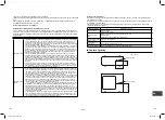
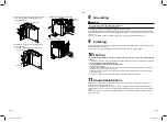
Barriers in front and back of unit
Open above and to the right and left of the unit.
The height of an barrier in both the front and rear of
the unit, should be lower than the height of the outdoor
unit.
▼
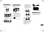
Standard installation
1. Single unit installation
5.9” (150)
or more
39.4” (1000)
or more
2. Multiple unit installation
a. Intake and supply parallel
7.9” (200)
or more
39.4” (1000)
or more
11.8” (300) or more
11.8” (300)
or more
b. Intake and supply in line
Open above and to the right and left of the unit.
The height of an obstacle in both the front and
rear of the unit should be lower than the height
of the outdoor unit.
▼
Standard installation
39.4”
(1000)
or more
11.8”
(300) or
more
59.1”
(1500)
or more
78.7”
(2000)
or more
7.9”
(200)
or more
■
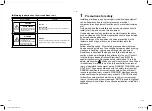
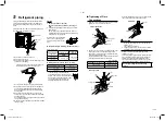
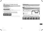
Installation of Outdoor Unit
•
Before installation, check the strength and horizontal
of the base so that abnormal sounds do not
emanate.
•
According to the following base diagram,
fi
x the
base
fi
rmly with the anchor bolts.
(Anchor bolt, nut: 3/8” (M10) x 4 pairs)
5.9” (150)
20.7” (525)
1.8” (45)
23.6” (600)
15.8
” (40
0)
14.4”
(365)
5.9” (150)
Drain hole
Drain connector
mounting hole
Drain hole
1) Field fabricate a snow or an ice stand for the
unit using the above dimension.
2) Place snow or ice stand on a foundation/pad
and secure it to the foundation/pad and secure
it to the foundation/pad by anchor bolts.
NOTE
When the outdoor unit is anchored directly on
the foundation/pad (cooling only protrude a
minimum of 0.6” (15 mm)).
0.6” (15 mm) or less
3) Place unit on stand. Make sure it is level and
fasten securely to the stand.
•
As shown in the
fi
gure below, install the
foundation and vibration-proof rubber pads
to directly support the bottom surface of the
fi
xing leg that is in contact with the bottom
plate of the outdoor unit.
•
When installing the foundation for an outdoor
unit with downward piping, consider the
piping work.
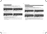
GOOD
GOOD
NO GOOD
NO GOOD
GOOD
GOOD
Mounting leg
Foundation
Bottom plate
of outdoor unit
Foundation
Support the bottom surface of the
mounting leg that is in contact with
and underneath the bottom plate of
the outdoor unit.
If only the end of the
mounting leg is
supported, it may
deform.
Do not support
the outdoor unit
only with the
mounting leg.
Foundation
•
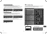
When water is to be drained through the drain hose,
attach the following drain connector and waterproof
rubber cap, and use the drain hose (Inner diameter:
0.6” (16 mm))
fi
eld supplied drain hose. Also seal
the screws securely with silicone material, etc.,
to prevent water from leaking.
Some conditions may cause condensation or
dripping of water.
•
When collectively draining discharged water
completely, use a drain pan.
Drain connector
Waterproof rubber cap
(5pcs.)
Drain connector
Waterproof rubber cap
■
For Reference
If a heating operation is to be continuously performed
for a long time under the condition that the outdoor
temperature is 32 °F (0 °C) or lower, draining
defrosted water may be difficult due to the bottom
plate freezing, resulting in trouble with the cabinet or
fan.
EN
TH
ID
15-EN
16-EN
1131601101 EN FR ES.indb 8
1131601101 EN FR ES.indb 8
4/8/2565 BE 10:14
4/8/2565 BE 10:14

