background image

– 10 –

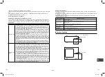
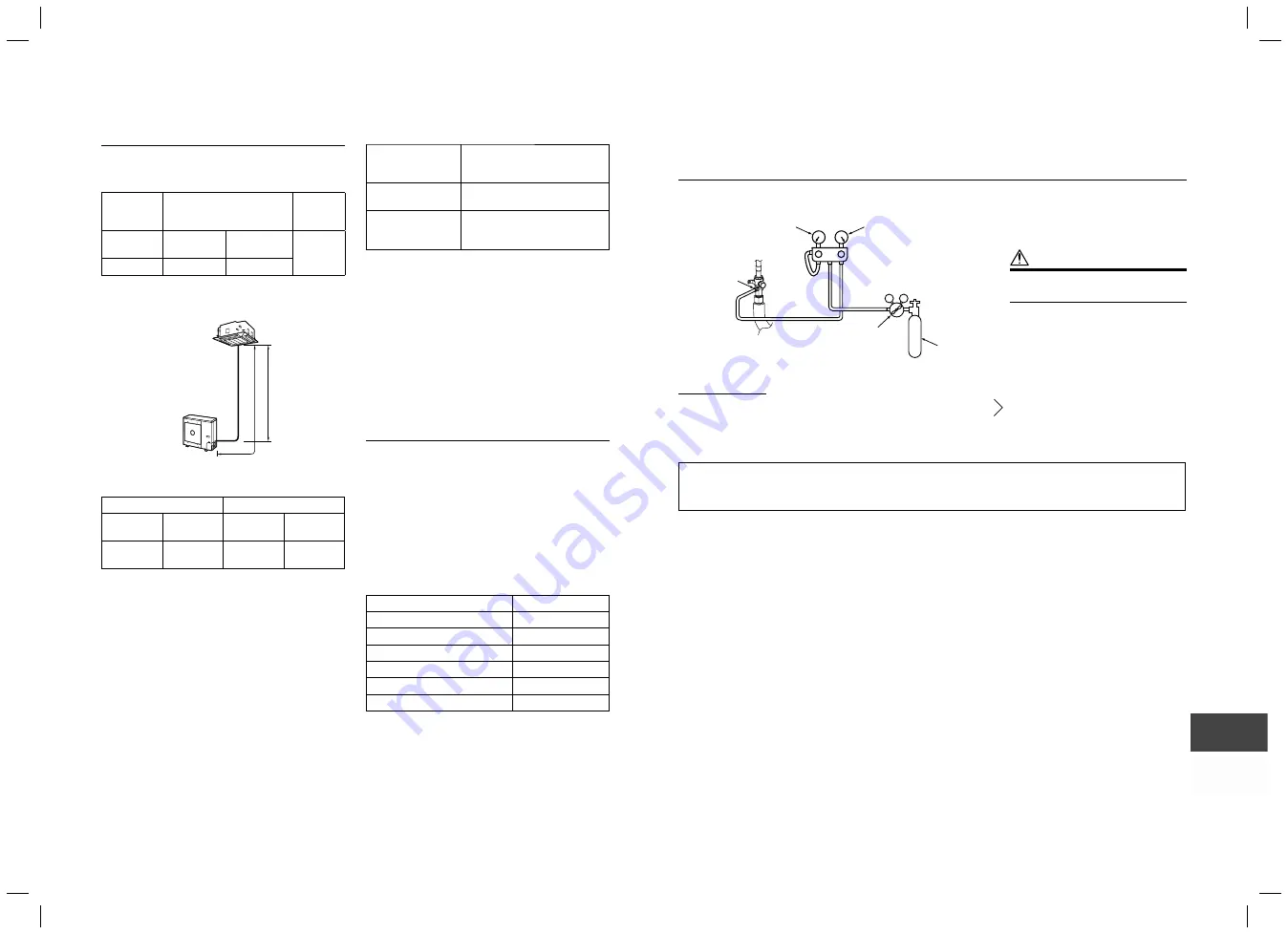
System Requirements

Minimum refrigerant line length between the outdoor 
unit and indoor unit is 16

5” (5 m)

Maximum pipe lengths

Allowable

pipe length

(ft (m))

Height difference

(Indoor-outdoor H)

(ft (m))

Number 

of bent 

portions

Total length

L

Indoor unit:

Upper

Outdoor unit:

Lower

10 or less

164’1” (50)

98’5” (30)

98’5” (30)

Figure of Single

H

L

Indoor Unit

Outdoor Unit

Refrigerant sizes

Liquid side

Gas side

Outer

diameter

Thickness

Outer

diameter

Thickness

Ø3/8”

(9.5 mm)

0.03”

(0.8 mm)

Ø5/8”

(15.9 mm)

0.04”

(1.0 mm)

Flare nuts and 

fl

 aring

The 

fl

 are nuts and 

fl

 aring are different from those for 

the conventional refrigerant.
Use the flare nuts supplied with the air conditioner or 
those for R410A.

Before performing 

fl

 aring, carefully read 

“REFRIGERANT PIPING”

Insulation (Local supplied)

Both lines need to be insulated. Use a minimum 0.4” 
(10 mm) wall thickness.

Refrigerant charge

Length of refrigerant 

pipe connected to 

indoor/outdoor unit

Additional refrigerant

16’5” - 98’5”

(5 - 30 m)

None

*98’5” - 246’1”

(30 - 75 m)

Add 0.43 oz/ft (40 g/m) of 
refrigerant for piping that exceeds 
98’5” (30 m) up to 246’1” (75 m).

*

Caution during addition of refrigerant 
Max. amount of additional refrigerant is 1.8 lbs 
(800 g). 
Charge the refrigerant accurately. Overcharging 
may cause serious trouble with the compressor.

*

Minimum refrigerant pipe is 16’5” (5 m). 
This may cause a malfunction of the compressor or 
other devices.

Metering Device is an electronic EXV (PMV) in 
outdoor unit.

Connecting power and control
cables (Field supplied)

The main power is supplied to the outdoor unit. 
The 

fi

 eld supplied connecting cables from the 

outdoor unit to the indoor unit consist for 4 wires 
and provides the power for the indoor unit as well as 
the communication signal between the outdoor and 
indoor unit.

System interconnection wire size must be AWG16.

Breaker must have a capacity speci

fi

 ed in the 

following table.

All wiring must comply with local electric codes and 
NEC (National Electric Code) or CEC (Canadian 
Electric Code).

Model RAV- 

SP242

Power supply

208/230 V, 60 Hz

MCA

17 A

MOCP (MAX Fuse/CB)

25 A

Breaker

20 A

System interconnection wires

AWG16

Field power supply wire

AWG12

MCA = Minimum Circuit Amps
MOCP = Maximum Over Protection Device Amps.

6

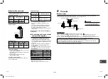
 Vacuum

Vacuum test

After completing the refrigerant piping work, perform a vacuum test. Connect a nitrogen gas cylinder and 
pressurize the pipes with nitrogen gas as follows to conduct the vacuum test.

 CAUTION

Never use oxygen, flammable gas, 
or noxious gas for the airtight test.

V

L

V

H

Low pressure gauge

Charge port

High pressure gauge

Pressure reducing 

valve

Nitrogen gas

Gauge manifold

Gas leak check

Step 1....Pressurize to 

0.5 MPa

 (5 kg/cm²G) for 5 minutes or longer. 

 Major leaks can be discovered.

Step 2....Pressurize to 

1.5 MPa

 (15 kg/cm²G) for 5 minutes or longer.

Step 3....Pressurize to 

4.15 MPa

 (42 kg/cm²G) for 24 hours. ................ Micro leaks can be discovered.

(However, note that when the ambient temperature differs during pressurization and after 24 hours, the pressure 
will change by approximately 0.01 MPa (0.1 kg/cm²G) per 1°C, so this should be compensated.)

If the pressure drops in steps 1 through 3, check the connections for leakage.
Check for leaks with foaming liquid, etc., take steps to fix the leaks such as brazing the pipes again and 
tightening the flare nuts, and then perform the airtight test again.

*

After the vacuum test is completed, evacuate the nitrogen gas.

EN

TH

ID

19-EN

20-EN

1131601101 EN FR ES.indb   10

1131601101 EN FR ES.indb   10

4/8/2565 BE   10:14

4/8/2565 BE   10:14

Содержание RAV-SP242AT2P-UL

Страница 1: ...door Unit Model name For commercial use Pour usage commercial Para uso comercial Heat Pump Model RAV SP242AT2P UL 1131601101 English Installation Manual 1 English 1131601101 EN FR ES indb 1 1131601101 EN FR ES indb 1 4 8 2565 BE 10 14 4 8 2565 BE 10 14 ...

Страница 2: ...er uses R410A an environmentally friendly refrigerant Contents 1 Precautions for safety 3 2 Accessory parts 5 3 Installation of R410A refrigerant air conditioner 6 4 Installation conditions 6 5 Refrigerant piping 9 6 Vacuum 10 7 Electrical work 12 8 Grounding 13 9 Finishing 13 10 Test run 13 11 Annual maintenance 13 12 Functions to be implemented locally 14 13 Troubleshooting 16 14 Appendix 17 15 ...

Страница 3: ...s a person who installs repairs maintains relocates and removes the air conditioners made by Manufacturer He or she has been trained to install repair maintain relocate and remove the air conditioners made by Manufacturer or alternatively he or she has been instructed in such operations by an individual or individuals who have been trained and is thus thoroughly acquainted with the knowledge relat...

Страница 4: ...autions in the literature and on tags stickers and labels attached to the equipment Follow all safety codes Wear safety glasses and work gloves Keep quenching cloth and fire extinguisher nearby when brazing Use care in handling rigging and setting bulky equipment Read these instructions thoroughly and follow all warnings or cautions included in literature and attached to the unit Consult local bui...

Страница 5: ...t gas has leaked during the installation work ventilate the room immediately If the leaked refrigerant gas comes in contact with fire noxious gas may be generated After the installation work confirm that refrigerant gas does not leak If refrigerant gas leaks into the room and flows near a fire source such as a cooking range noxious gas may be generated Electrical work must be performed by a qualif...

Страница 6: ...ause burst and injure CAUTION Do not climb onto or place objects on top of the outdoor unit You may fall or the objects may fall off of the outdoor unit and result in injury Wear heavy gloves during the installation work to avoid injury EQUIPMENT DAMAGE HAZARD Failure to follow this caution may result in equipment damage or improper operation Do not bury more than 36 in 914 mm of refrigerant pipe ...

Страница 7: ...ected to indoor outdoor unit Item RAV SP242AT2P UL 16 5 to 164 1 5 to 50 m Addition of refrigerant at the local site in unnecessary for refrigerant pipe lengths up to 98 5 30 m If the reftigerant pipe length exceeds 98 5 30 m Add refrigerant in the amount given in Charging additional refrigerant Caution during addition of refrigerant Charge the refrigerant accurately Overcharging may cause serious...

Страница 8: ...n where the operating noise of the outdoor unit is transmitted When the outdoor unit is installed in an elevated position be sure to secure its feet A location in which drain water poses any problems When an outdoor unit is installed in a location that is always exposed to strong winds like a coast or on the high stories of a building one of the following is recommended Install the unit so that it...

Страница 9: ...m or less 3 Place unit on stand Make sure it is level and fasten securely to the stand As shown in the figure below install the foundation and vibration proof rubber pads to directly support the bottom surface of the fixing leg that is in contact with the bottom plate of the outdoor unit When installing the foundation for an outdoor unit with downward piping consider the piping work GOOD GOOD NO G...

Страница 10: ...g diameter size A Unit in mm Outer diameter of copper pipe A 0 0 02 0 4 3 8 9 5 0 52 13 2 5 8 15 9 0 78 19 7 In case of flaring for R410A with the conventional flare tool pull the tool out approx 0 02 0 5 mm more than that for R22 to adjust it to the specified flare size The copper pipe gauge is useful for adjusting the projection margin size A Tightening of Flare Connections 1 Align the centers o...

Страница 11: ...ovides the power for the indoor unit as well as the communication signal between the outdoor and indoor unit System interconnection wire size must be AWG16 Breaker must have a capacity specified in the following table All wiring must comply with local electric codes and NEC National Electric Code or CEC Canadian Electric Code Model RAV SP242 Power supply 208 230 V 60 Hz MCA 17 A MOCP MAX Fuse CB 2...

Страница 12: ...ion Method chart EVACUATE BREAK VACUUM WITH DRY NITROGEN WAIT EVACUATE BREAK VACUUM WITH DRY NITROGEN WAIT EVACUATE CHECK FOR TIGHT DRY SYSTEM IF IT HOLDS DEEP VACCUM RELEASE CHARGE INTO SYSTEM Final Tubing Check IMPORTANT Check to be certain factory tubing on both indoor and outdoor unit has not shifted during shipment Ensure tubes are not rubbing against each other or any sheet metal Pay close a...

Страница 13: ...lowing table All wiring must comply with local electric codes and NEC National Electric Code or CEC Canadian Electric Code Model RAV SP242 Power supply 208 230 V 60 Hz MCA 17 A MOCP MAX Fuse CB 25 A Breaker 20 A System interconnection wires AWG16 Field power supply wire AWG12 MCA Minimum Circuit Amps MOCP Maximum Over Protection Device Amps Connect the system interconnection indoor to outdoor wire...

Страница 14: ...d piping 10Test run Turn on the leakage breaker at least 12 hours before starting a test run to protect the compressor during startup To protect the compressor power is supplied from the 208 230 VAC input to the unit to preheat the compressor Check the following before starting a test run That all pipes are connected securely without leaks That the valve is open If the compressor is operated with ...

Страница 15: ...4 Yellow D805 Green or or or or or OFF or Rapid flashing OFF or Rapid flashing OFF or Rapid flashing OFF or Rapid flashing OFF or Rapid flashing ON 12Functions to be implemented locally Handling existing pipe When using the existing pipe carefully check for the following Wall thickness within the specified range Scratches and dents Water oil dirt or dust in the pipe Flare looseness and leakage fro...

Страница 16: ... least 5 seconds to return to the initial status and then repeat the setting steps Steps taken to recover the refrigerant 1 Operate the indoor unit in the fan mode 2 Check that the LED displays are placed in their initial status If not place them in the initial status 3 Hold down SW01 for at least 5 seconds and check that D804 flashes slowly Fig 1 4 Press SW01 once to set the LED displays D800 to ...

Страница 17: ...ou can check whether the existing piping settings are enabled 1 Check that the LED displays are placed in their initial status If not place them in the initial status 2 Hold down SW01 for at least 5 seconds and check that D804 flashes slowly Fig 9 3 Press SW01 four times to set the LED displays D800 to D805 to the LED displays for existing piping settings shown below If the setting is enabled D802...

Страница 18: ...ness R410A 0 03 0 8 0 04 1 0 3 When the outdoor unit was left with the pipes disconnected or the gas leaked from the pipes and the pipes were not repaired and refilled There is the possibility of rain water or air including moisture entering the pipe 4 When refrigerant cannot be recovered using a refrigerant recovery unit There is the possibility that a large quantity of dirty oil or moisture rema...

Страница 19: ...o prevent the writing from rubbing off 3 Prevent emission of the contained fluorinated greenhouse gas Ensure that the fluorinated greenhouse gas is never vented to the atmosphere during installation service or disposal When any leakage of the contained fluorinated greenhouse gas is detected the leak shall be stopped and repaired as soon as possible 4 Only qualified service personnel are allowed to...

Страница 20: ...4 9 Moo 5 Bangkadi Industrial Park Tivanon Road Tambol Bangkadi Amphur Muang Pathumthani 12000 Thailand 1131601101 1131601101 EN FR ES indb 2 1131601101 EN FR ES indb 2 4 8 2565 BE 10 14 4 8 2565 BE 10 14 ...

Отзывы: