– 55 –
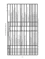
No.
11
Item
Filter sign display
Outline of specifications
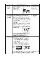
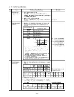
1) The operation time of the indoor fan is calculated, the filter
lamp (Orange) on the display part of the main unit goes on
when the specified time (240H) has passed. When a wired
remote controller is connected, the filter reset signal is sent to
the remote controller, and also it is displayed on LCD of the
wired remote controller.
2) When the filter reset signal has been received from the wired
remote controller after [FILTER] lamp has gone on or when
the filter check button (Temporary button) is pushed, time of
the calculation timer is cleared. In this case, the measurement
time is reset if the specified time has passed, and display on
LCD and the display on the main unit disappear.
Remarks
[FILTER] goes
on.
12
13
14
Setup on central
control remote
controller
Last push priority
Center
Operation prohibited
Display on wired remote
controller
(In case of RBC-AM1)
[Central control] goes off.
[Central control] goes on.
[Central control] flashes.
Display on wired
remote controller
(In case of RBC-AM1)
[Center] goes off.
[Center] goes on.
[Center] flashes.
Display on main unit
(Only in case of no wired remote
controller)
No display
[DEFROST] lamp (Orange) 1Hz flashes.
[DEFROST] lamp (Orange) 5Hz flashes.
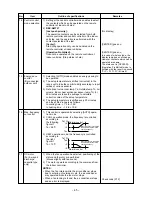
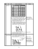
1) Setting at the central remote controller side enables to select the contents which
can be operated on the remote controller at indoor unit side.
2) Operation contents on the remote controller at indoor unit side
[Last push priority] :
The operation contents can be selected from both remote controller and the
central controller of the indoor unit side, and the operation is performed with the
contents selected at the last.
[Center] :
Start/Stop operation only can be handled on the remote controller at indoor unit
side.
[Operation Prohibited] :
It cannot be operated on the remote controller at indoor unit side.
(Stop status is held.)
3) Display on the display part of the main unit or wired remote controller
Energy-save
control
(By connected
outdoor unit)
NOTE : When a wired remote controller is connected, there is no display on the main unit.
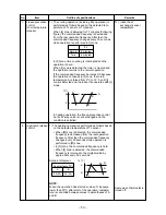
1) Selecting [AUTO] mode enables an energy-saving to be operated.
2) The setup temperature is shifted (corrected) in the range not to lose the comfort
ability according to input values of various sensors.
3) Data (Input value room temp. Ta, Outside temp. To, Air volume, Indoor heat
exchanger sensor temp. Tc) for 20 minutes are taken the average to calculate
correction value of the setup temperature.
4) The setup temperature is shifted every 20 minutes, and the shifted range is as
follows.
In cooling time : +1.5 to –1.0K
In heating time : –1.5 to +1.0K
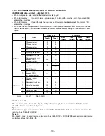
1) This control is operated by selecting
[AUTO] operation mode.
2) COOL operation mode: the fre-
quency is controlled according to the
following figure if To < 28°C.
Max. frequency
cut control
3) HEAT operation mode: the frequency
is controlled according to the right
figure if To > 15°C.
Central control
mode selection
+4
+3
Tsc
Tsh
-3
-4
Ta(˚C)
Ta(˚C)
Normal control
Normal control
Max. frequency is restricted
to approximately the rated
cooling frequency
Max. frequency is restricted
to approximately the rated
heating frequency


