background image

Installation Manual

 31 

31-EN

„

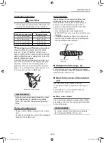
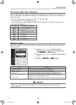
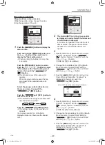
To secure better effect of heating

When it is dif

fi

cult to obtain satisfactory heating due to installation place of the indoor unit or structure of 

the room, the detection temperature of heating can be raised. Also use a circulator, etc. to circulate heat 
air near the ceiling.
Follow to the basic operation procedure (

1


2


3


4


5


6

).

•  For the CODE No. in Procedure 

3

, specify [06].

•  For the SET DATA in Procedure 

4

, select the SET DATA of shift value of detection temperature to be 

set up from the table below.

SET DATA

Detection temp shift value

0000

No shift

0001

1.8°F (+1°C)

0002

3.6°F (+2°C) (Factory setting)

0003

5.4°F (+3°C)

0004

7.2°F (+4°C)

0005

9.0°F (+5°C)

0006

10.8°F (+6°C)

„

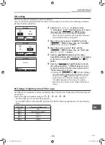
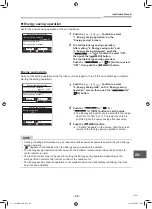
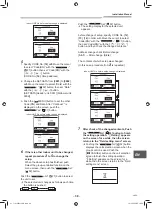
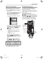
Energy saving

Set for the energy saving operation: Energy saving operation, Set temp. range limit, Return back and 
Saving operation.

Energy saving(1/2)

1.Energy saving operation

2.Set temp. range limit
3.Return back

<ON>

<OFF>

Set

Return

1

Push the [


3

] / [


4

] button to select 

“Energy saving” on the menu screen, then push 
the “

Set

 Set” [  F2] button.

2

Push the [


3

] / [


4

] button to select the item 

to set.

3

Push the “

Set

 Set” [  F2] button.

Item

Function

1. Energy saving operation

Perform the power saving operation of the air conditioner.

2. Set temp. range limit

Set the temperature range limit of the remote control operation.

3. Return back

Set the function that changes the temperature back to the speci

fi

ed temperature 

automatically if the temperature has been changed on the remote control.

4. Saving operation

Performs operation by suppressing excessive heating or excessive cooling through 
automatic correction of the temperature set point.
*  “No function” is displayed in the case of a model for which the saving operation cannot 

be set.

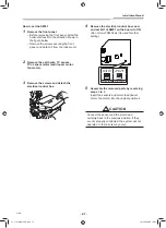
 CAUTION

Refer to the Owner’s Manual supplied with the air conditioner about “Energy saving operation”, 
“Saving operation”.

01_1121250414-EN.indd   31

01_1121250414-EN.indd   31

14/1/2565 BE   16:50

14/1/2565 BE   16:50

Содержание RAV-SM122KRTP-UL

Страница 1: ...122KRTP UL RAV SM182KRTP UL RAV SM242KRTP UL Installation Manual 1 English 1121250414 For commercial use Pour usage commercial Para uso comercial AIR CONDITIONER SPLIT TYPE 00_1121250414 Cover indd 1 00_1121250414 Cover indd 1 23 12 2564 BE 17 49 23 12 2564 BE 17 49 ...

Страница 2: ...ses R410A an environmentally friendly refrigerant Contents 1 PRECAUTIONS FOR SAFETY 5 2 ACCESSORY PARTS 11 3 SELECTION OF INSTALLATION PLACE 12 4 INSTALLATION OF INDOOR UNIT 14 5 CUTTING A HOLE AND MOUNTING INSTALLATION PLATE 16 6 PIPING AND DRAIN HOSE INSTALLATION 17 7 INDOOR UNIT FIXING 21 8 DRAINAGE 21 9 REFRIGERANT PIPING 22 10 ELECTRICAL CONNECTION 25 11 APPLICABLE CONTROLS 29 12 TEST RUN 43 ...

Страница 3: ...r individuals who have been trained and is thus thoroughly acquainted with the knowledge related to this work The qualified installer who is allowed to work at heights has been trained in matters relating to working at heights with the air conditioners made by Toshiba Carrier Corporation or alternatively he or she has been instructed in such matters by an individual or individuals who have been tr...

Страница 4: ...e and damages to property Please read through this manual after understanding the contents below meanings of indications and be sure to follow the description Indication Meaning of Indication WARNING Text set off in this manner indicates that failure to adhere to the directions in the warning could result in serious bodily harm 1 or loss of life if the product is handled improperly CAUTION Text se...

Страница 5: ...the unit before the servicing CAUTION High temperature parts You might get burned when removing this panel CAUTION High temperature parts You might get burned when removing this panel CAUTION Do not touch the aluminum fins of the unit Doing so may result in injury CAUTION Do not touch the aluminium fins of the unit Doing so may result in injury CAUTION BURST HAZARD Open the service valves before t...

Страница 6: ...nt from the one specifled for complement or replacement Otherwise abnormally high pressure may be generated in the refrigeration cycle which may result in a failure or explosion of the product or an injury to your body Before opening the front panel of the indoor unit set the circuit breaker to the OFF position Failure to set the circuit breaker to the OFF position may result in electric shocks th...

Страница 7: ...ople Do not move or repair any unit by yourself Must be done by qualified installer or qualified service person Special precaution should be taken when removing the cover for the unit to avoid electric shock from high voltage lines This appliance is intended to be used by expert or trained users in shops in light industry or for commercial use by lay persons Selection of installation location When...

Страница 8: ...nd without refrigerant pipe the compressor sucks air and the refrigeration cycles is over pressurized which may cause a injury Tighten the flare nut with a torque wrench in the specified manner Over tightening of the flare nut may cause a crack in the flare nut after a long period which may result in refrigerant leakage After the installation work confirm that refrigerant gas does not leak If refr...

Страница 9: ...er no circumstances the power wire must not be extended Connection trouble in the places where the wire is extended may give rise to smoking and or a fire Electrical wiring work shall be conducted according to law and regulation in the community and installation manual Failure to do so may result in electrocution or short circuit Test run Before operating the air conditioner after having completed...

Страница 10: ...but set the circuit breaker to the OFF position and contact a qualified service person to have the repairs done Do not set the circuit breaker to the ON position until the repairs are completed After the installation work follow the Owner s Manual to explain to the customer how to use and maintain the unit Relocation Only a qualified installer or qualified service person is allowed to relocate the...

Страница 11: ...n unit and installation tools are changed from those for the conventional refrigerant Accordingly the exclusive tools are required for the new refrigerant R410A For connecting pipes use new and clean piping designed for R410A and please care so that water or dust does not enter To disconnect the appliance from main power supply This appliance must be connected to the main power supply by means of ...

Страница 12: ...and over to customers Installation plate 1 Wireless remote controller 1 Battery 2 Remote controller holder 1 Mounting screw Ø5 32 4 mm 1 0 25 mm 6 Flat head wood screw Ø1 8 3 1 mm 0 6 16 mm 2 Screw Ø5 32 4 mm 0 4 10 mm 2 Heat insulator 1 Eletrical cover 2 holes 1 01_1121250414 EN indd 11 01_1121250414 EN indd 11 14 1 2565 BE 16 50 14 1 2565 BE 16 50 ...

Страница 13: ...ch as kitchens where food oils are used Blocked filters may cause the air conditioner s performance to deteriorate condensation to form the plastic parts to be damaged and other such problems to result Locations near obstructions such as ventilation openings or lighting fixtures where the flow of the blown air will be disrupted a disruption of the air flow may cause the air conditioner s performan...

Страница 14: ... and for service work Keep 4 3 110 mm or more for clearance between top plate of the indoor unit and the ceiling surface 2 Provide a space as shown for service clearance for the cross flow fan Installation place A place which provides the spaces around the indoor unit as shown in the above diagram A place where there is no obstacle near the air inlet and outlet A place that allows easy installatio...

Страница 15: ...o guard against strong wind or earthquake An incomplete installation can cause accidents by the units falling and dropping REQUIREMENT Strictly comply with the following rules to prevent damage of the indoor units and human injury Do not put a heavy article on the indoor unit Even units are packaged Carry in the indoor unit as it is packaged if possible If carrying in the indoor unit unpacked by n...

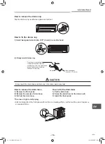
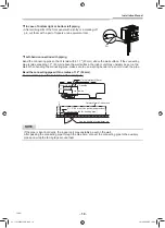
Страница 16: ...e the screw 1 part 2 Remove the electrical cover 1 hole by direction backside of unit Direction to remove 3 Remove the EDGE SADDLE take off from electrical cover 1 hole Direction to remove Step to install the electrical cover 1 hole Option connect power supply 2 holes 1 Install the EDGE SADDLE to electrical cover 1 hole 2 Install the electrical cover 1 hole to unit 3 Insert the screw Make sure to ...

Страница 17: ... the indoor unit fit to the wall 3 3 85 mm 6 7 2 m or more from floor When the installation plate is directly mounted on the wall 1 Securely fit the installation plate onto the wall by screwing it in the upper and lower parts to hook up the indoor unit 2 To mount the installation plate on a concrete wall with anchor bolts utilize the anchor bolt holes as illustrated in the above figure 3 Install t...

Страница 18: ...he front panel for the bottom left or right connection with a pair of nippers 2 Changing drain hose For leftward connection bottom leftward connection and rear leftward connection s piping it is necessary to change the drain hose and drain cap How to remove the drain hose The drain hose can be removed by removing the screw securing the drain hose and then pulling out the drain hose When removing t...

Страница 19: ...nd drain leakage from the plug CAUTION Firmly insert the drain hose and drain cap otherwise water may leak How to remove the drain hose 1 Remove the front panel 2 Remove the screws of drain hose 3 Pull out the drain hose How to fix the drain hose 1 Put the drain hose 2 Screw the drain hose to the indoor unit 3 Install the front panel q In case of right or left piping After scribing slits of the fr...

Страница 20: ...to use a spring bender so as not to crush the pipe Bend the connecting pipe within a radius of 1 2 30 mm To connect the pipe after installation of the unit figure 22 4 570 mm 16 5 420 mm 1 7 43 mm Liquid side Gas side To the forefront of flare Outward form of indoor unit R 1 2 30 mm Use polisin polyethylene core or the like for bending pipe Use the handle of screwdriver etc 80 NOTE If the pipe is ...

Страница 21: ...ard the ceiling surface CAUTION Bind the auxiliary pipes two and power supply wiring and control wiring with facing tape tightly In case of leftward piping and rear leftward piping bind the auxiliary pipes two only with facing tape Indoor unit Power supply wiring Control wiring Auxiliary pipes Installation plate Carefully arrange pipes so that any pipe does not stick out of the rear plate of the i...

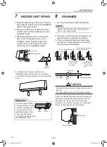
Страница 22: ...fix the unit and the installation plate Screw Screw 1 Run the drain hose sloped downwards NOTE Hole should be made at a slight downward slant on the outdoor side 2 Put water in the drain pan and make sure that the water is drained out of doors 3 When connecting extension drain hose insulate the connecting part of extension drain hose with shield pipe 2 50 mm or more Do not rise the drain hose Do n...

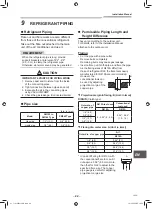
Страница 23: ...the Installation Manual attached to the outdoor unit Flaring ෬ Cut the pipe with a pipe cutter Remove burrs completely Remaining burrs may cause gas leakage ෬ Insert a flare nut into the pipe and flare the pipe As the flaring sizes of R410A differ from those of refrigerant R22 the flare tools newly manufactured for R410A are recommended However the conventional tools can be used by adjusting proje...

Страница 24: ... manufactured exclusively HFC refrigerant R410A R134a etc Tightening connection CAUTION Do not apply excessive torque Otherwise the nut may crack depending on the conditions Unit in mm Outer dia of copper pipe Tightening torque 1 4 6 4 mm dia 10 13 14 18 3 8 9 5 mm dia 24 31 33 42 1 2 12 7 mm dia 37 46 50 62 5 8 15 9 mm dia 50 60 68 82 q Tightening torque of flare pipe connections Pressure of R410...

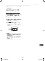
Страница 25: ...unit 3 Push and hold button on the wireless remote controller by the tip of the pencil 00 will be shown on the display 4 Push during pushing B will be shown on the display and 00 will be disappear and the air conditioner will turn OFF The wireless remote controller B is memorized B Display 00 Display NOTE Repeat above step to reset wireless remote controller to be A The wireless remote controllers...

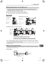
Страница 26: ...ture part of the pipe The coating may melt resulting in an accident Do not turn on the power of the indoor unit until vacuuming of the refrigerant pipes completes System interconnection wires specifications System interconnection wires AWG16 or more H07RN F or 60245 IEC 66 Up to 229 7 70 m Number of wire wire size Remote controller wiring Remote controller wiring remote controller inter unit wirin...

Страница 27: ...emote controller wiring System interconnection wires Power supply Indoor side Indoor side Indoor side Indoor power inter unit wiring Indoor power inter unit wiring Indoor power inter unit wiring Remote controller inter unit wiring Remote controller inter unit wiring Remote controller inter unit wiring Triple Double twin Use 2 core shield wire MVVS AWG20 to AWG16 for the remote controller wiring in...

Страница 28: ...to the terminal block and secure it tightly with screws Tightening torque 0 9 ft lbs 1 2 N m Secure the earth line with the earth screw 9 Clamp the power supply wire with the cord clamp 10 Attach the terminal cover and the air inlet grille to the indoor unit CAUTION Be sure to refer to the wiring diagram attached inside the front panel Check local electrical cords an also any specific wiring instr...

Страница 29: ...e the system interconnection wire and wired remote controller wire out of the cable slot on the rear panel so that it protrudes about 5 9 150 mm from the front 5 Insert the wired remote controller wire fully into the wired remote controller central control terminal block A B and secure it tightly with screws Strip off approx 0 3 9 mm the wire to be connected Non polarity 2 core wire is used for wi...

Страница 30: ...r conditioner or other trouble with the product may result Field setting menu 1 Test mode 2 Register service info 3 Alarm history 4 Monitor function 5 Setting louver position Field setting menu Return Set 1 Push the MENU button to display the menu screen Push and hold the MENU button and the 4 button at the same time to display the Field setting menu Æ Push and hold the buttons for more than 4 sec...

Страница 31: ...ntinue is displayed on the screen push the Yes Yes F1 button 6 Push the No No F2 button to finish the setting operation Setting appears on the screen for a while then the screen returns to the Field setting menu screen Æ Pushing the No No F2 button displays the unit selection screen when the group control is used Push the CANCEL button on the unit selection screen to finish the setting operation S...

Страница 32: ...ng operation 2 Set temp range limit 3 Return back ON OFF Set Return 1 Push the 3 4 button to select Energy saving on the menu screen then push the Set Set F2 button 2 Push the 3 4 button to select the item to set 3 Push the Set Set F2 button Item Function 1 Energy saving operation Perform the power saving operation of the air conditioner 2 Set temp range limit Set the temperature range limit of th...

Страница 33: ...urn Fix 1 Push the 3 4 button to select 2 Energy saving ratio on the Energy saving operation screen then push the Set Set F2 button 2 Push the F1 F2 button to set the value Æ The Energy saving ratio can be set within the range from 50 to 100 by 1 The lower the value is set the higher the power saving effect becomes 3 Push the MENU button Æ Setting appears on the screen then the screen returns to t...

Страница 34: ...ta CODE No Data name 60 Outdoor unit heat exchanger coil temperature TE 61 Outside air temperature TO 62 Compressor discharge temperature TD 63 Compressor suction temperature TS 64 65 Heatsink temperature THS 6A Operating current x1 10 F1 Compressor cumulative operating hours x100h Adjustment of air direction 1 Using the remote controller switch change the up down air direction by moving the horiz...

Страница 35: ...the Swing OFF Swing OFF F2 button on the Wind direction screen Æ Push the Swing OFF Swing OFF F2 button to stop swinging The louver stops in the position where the button is pushed The louver does not stop in the position 4 or 5 when the operation mode is Cool or Dry The louver stops in the position 3 even if the button is pushed when the louver is in the position 4 or 5 Fan Heat Display when the ...

Страница 36: ... Remote controller Indoor unit Indoor unit Finish of address setup by power ON q Double twin Outdoor unit Indoor unit Remote controller Indoor unit Indoor unit Indoor unit Finish of address setup by power ON For wiring procedure and wiring method follow to the Electrical connection in this manual When the power supply has been turned on the automatic address setup starts and which indicates that a...

Страница 37: ...sing is approx 5 minutes NOTE In some cases it is necessary to change the address manually after setup of the automatic address according to the system configuration of the group control The follow mentioned system configuration is a case when complex systems in which systems of the simultaneous twin and simultaneous triple unit is controlled as a group by a remote controller Example Group control...

Страница 38: ...header unit 2 The indoor UNIT No in the group control is displayed in order Select the indoor unit of which setup is changed In this time the position of the indoor unit of which setup is changed can be confirmed because fan of the selected indoor unit operate 3 1 Specify CODE No 12 with Move the cursor to select Code DN with the 1 F1 button then set Code DN with the 3 4 button CODE No 12 Line add...

Страница 39: ...s as follows each time the button is pushed 1 1 1 2 1 8 Push the Set Set F2 button Æ The setting display for the selected unit appears before change of setup specify CODE No 12 13 14 in order with Move the cursor to select Code DN with the 1 F1 button then set Code DN with the 3 4 button and then check the changed contents Address change check Before change 3 3 1 After change 2 2 2 The contents of...

Страница 40: ...ATA 46 F 8 C Operation setting 0000 None Factory default 0001 46 F 8 C Operation setting Push the CANCEL button to return Central control system Air conditioners at multiple locations can be controlled individually for each refrigeration system from a control room Central control is not available with the supplied wireless remote controller Use the optional wired remote controller q Wiring for cen...

Страница 41: ...vice Central control device Central control device Up to 10 units Outdoor unit System interconnection wire 208 230 1 60 Central control wires Connect 1 and 2 only Follower indoor unit Follower indoor unit Indoor unit Follower indoor unit Header indoor unit Header indoor unit TCC LINK adapter option Required for indoor units other than high wall type Remote controller wiring Remote controller Remot...

Страница 42: ...the electrical control box cover and set bit1 of SW01 on the board to ON Do not touch SW02 as it is used for other setting SW01 OFF SW02 OFF SW01 ON SW02 OFF ON 1 2 ON 1 2 Factory default After setting 5 Assemble the removed parts by reversing steps 1 to 3 Insert the sensors and motor lead louver motor fan motor into the original positions CAUTION Connect the sensor and the motor lead certainly ba...

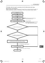
Страница 43: ...ress manual setting change Are indoor units under group control Are all indoor units under central control set to header units group address 1 Set indoor units under central control to header units again and set those that are out of central control to follower units again Refer to Manual address setup procedure No Refer to the manual of the central control system Yes Yes No The system performs th...

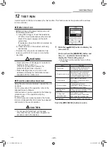
Страница 44: ...test run Before turning on the power supply carry out the following procedure 1 Using 500V megger check that resistance of 1MΩ or more exists between the terminal block of the power supply and the earth grounding If resistance of less than 1MΩ is detected do not run the unit 2 Check the valve of the outdoor unit being opened fully To protect the compressor at activation time leave power ON for 12 ...

Страница 45: ...ng RESET button for 10 seconds or more Pi sound is heard and the operation changes to a forced cooling operation After approx 3 minutes a cooling operation starts forcedly Check cool air starts blowing If the operation does not start check wiring again 2 To stop a test operation push RESET button once again Approx 1 second The louver closes and the operation stops OPERATION RESET button Check tran...

Страница 46: ...be opened further otherwise the arms may come off and the air intake grille may fall down Air filter Cleaning with water or vacuum cleaner If dirt is heavy clean the air filter by tepid water with neutral detergent or water After cleaning with water dry the air filter sufficiently in a shade place Mount the air filter 2 Turn on the circuit breaker then push the button on the remote controller to s...

Страница 47: ...ny clogging or damages Fan motor Access from inspection opening and check if any abnormal noise can be heard Fan Access from inspection opening and remove the access panel Examine the fan if there are any waggles damages or adhesive dust Filter Go to installed location and check if there are any stains or breaks on the filter Drain pan Access from inspection opening and remove the access panel Che...

Страница 48: ...t number of the indoor unit appear on the display of the remote control The check code appears only while the unit is running Push the MONITOR button or CANCEL button to display the check information screen Check Contact Information Return Check Code P10 Unit 2 2 While the check information screen appears Push the Contact Contact F1 button to display the contact number for service Push the Informa...

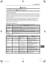
Страница 49: ...rol The header indoor unit stops raising alarm and follower indoor units continue to operate Е10 CPU CPU communication error Indoor Indoor P C board Communication error between main MCU and motor microcomputer MCU Auto reset E18 Header unit follower unit regular communication error Indoor Indoor P C board Regular communication is not possible between header and follower indoor units or between twi...

Страница 50: ...case thermostat Entire stop H06 Outdoor unit low pressure system error Outdoor Current high pressure switch circuit outdoor P C board Pressure sensor error was detected or low pressure protective operation was activated Entire stop L03 SIM Duplicated header indoor units Indoor Indoor address setting error There are two or more header units in the group Entire stop L07 SIM Group line in individual ...

Страница 51: ...ard or indoor DC fan over current or lock etc is detected Entire stop P15 ALT Gas leakage detected Outdoor There may be gas leakage from the pipe or connecting part Check for gas leakage Entire stop P19 ALT 4 way valve error Outdoor Indoor 4 way valve indoor temp sensors TC TCJ An error was detected due to temperature drop of the indoor unit heat exchanger sensor during heating Auto reset P20 ALT ...

Страница 52: ...14 144 9 Moo 5 Bangkadi Industrial Park Tivanon Road Tambol Bangkadi Amphur Muang Pathumthani 12000 Thailand 04_1121250414 Back cover indd 5 04_1121250414 Back cover indd 5 2 11 2564 BE 16 04 2 11 2564 BE 16 04 ...

Отзывы: