Installation Manual
‒
20
‒
20-EN
EN
FR
ES
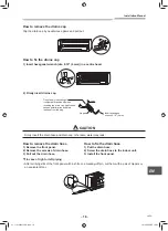
A
A
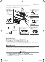
Heat insulator provided
Gas side
Indoor unit shield pipe
Liquid side
Cut the heat insulator of the gas pipe
(locally procured) leaving a 0.4
″
(10 mm)
overlap with the shield of the shield pipe.
0.4
″
(10 mm)
Heat insulator wrapping cross section A-A
Make the slit part of heat insulator to upward.
▼
Insulating the pipes
Insulate the indoor unit completely so there are no gaps using the heat insulator provided.
CAUTION
Securely apply insulation all the way up to the pipe connecting section of the indoor unit so that there
is no exposed area. (the pipe exposed to the outside causes water leak.)
When wrapping the heat insulator around pipes, make sure the slit aperture toward the ceiling surface.
CAUTION
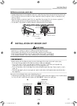
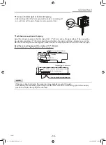
• Bind the auxiliary pipes (two) and power supply wiring and control wiring with facing tape tightly.
In case of leftward piping and rear leftward piping, bind the auxiliary pipes (two) only with facing tape.
Indoor unit
Power supply wiring
Control wiring
Auxiliary pipes
Installation plate
• Carefully arrange pipes so that any pipe does not stick out of the rear plate of the indoor unit.
• Carefully connect the auxiliary pipes and connecting pipes to one another and cut off the insulating
tape wound on the connecting pipe to avoid double-taping at the joint; moreover, seal the joint with
the vinyl tape, etc.
• Since dew results in a machine trouble, make sure to insulate both the connecting pipes.
(Use polyethylene foam as insulating material.)
• When bending a pipe, carefully do it, not to crush it.
01_1121250414-EN.indd 20
01_1121250414-EN.indd 20
14/1/2565 BE 16:50
14/1/2565 BE 16:50

