background image

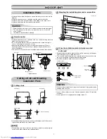
500

140

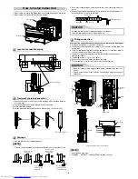
(Side view)

Partition board

20 to 30

Opening for receiver

(Front view)

800 or more

670 or more

Partition board

Opening for receiver

50 or more

50 or more

70 or more

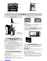
•  Check the fl are nut 

connections for the gas 
leak with a gas leak 
detector or soap water.

Gas Leak Test

Check places for fl are nut connection 
(Indoor unit)

Check places for the outdoor unit.

Valve cover

Remote control selector switch

  When two indoor units are installed in the same room or adjacent two 

rooms, if operating a unit, two units may receive the remote control 
signal simultaneously and operate. In this case, the operation can 
be preserved by setting either one indoor unit or remote control to B 
setting (Both are set to A setting in factory shipment).

  The remote control signal is not received when the settings of indoor 

unit and remote control are different.

  There is no relation between A setting/B setting and A room/B room 

when connecting the piping and cables.

When two indoor units are installed in the separated rooms, it is not 
necessary to change the selector switches.

Setting of Remote Control

Selector Switch

Remote Control A-B Selection

To separate using of remote control for each indoor unit in case of 2 air 
conditioners are installed nearly.

Remote Control B Setup.

1. Push and hold 

 button on the Remote Control by the tip of the pencil.

   “00” will be shown on the display (Picture 

1

).

2. Press 

 during pushing 

. “B” will show on the display and “00” will 

disappear and the air conditioner will turn OFF. The Remote Control B is 
memorized (Picture 

2

).

Note  :  1. Repeat above step to reset Remote Control to be A.
 

  2. Remote Control A has not “A” display.


  3. Default setting of Remote Control from factory is A.

Unit B setup. 

  Press and hold MODE button for more than 20 seconds. 
  When A setup changed to B setup : 5 beeps will sound and operation 

lamp blinks for 5 seconds. 

  When B setup changed to A setup : 5 beep will sound.

OTHERS

OTHERS

Test Operation

Auto Restart Setting

How to set the Auto Restart

1. Press and hold OPERATION button on the indoor unit for 3 seconds to set 

the operation (3 beep sound and OPERATION lamp blink 5 time/sec for 5 
seconds).

2. Press and hold OPERATION button on the indoor unit for 3 seconds to 

cancel the operation (3 beep sound but OPERATION lamp does not blink).


 In case of ON timer or OFF timer are set, it dose not activate.

This product is designed so that, after a power failure, it can restart 
automatically in the same operating mode as before the power failure.

To switch the TEST RUN (COOL) mode, press OPERATION button for 10 
seconds (The beeper will make a short beep).

Information

The product are shipped with Auto Restart function in the off position. 
Turn it on as required.

10

Содержание RAS-B10U2FVG-E

Страница 1: ...AIR CONDITIONER SPLIT TYPE INSTALLATION MANUAL Indoor unit RAS B10 13 18U2FVG E R32 1112151199 ...

Страница 2: ...tallation Parts 6 INDOOR UNIT 7 Installation Place 7 Cutting a Hole and Mounting Installation Plate 7 How to Install Indoor Unit 8 Concealed Installation 9 OTHERS 10 Gas Leak Test 10 Setting of Remote Control Selector Switch 10 Remote Control A B Selection 10 Test Operation 10 Auto Restart Setting 10 EN ...

Страница 3: ...e of appliance use shall be at least polychloroprene sheathed flexible cord design H07RN F or cord designation 60245 IEC66 Shall be installed in accordance with national wiring regulations CAUTION This appliance must be connected to the main power supply by means of a circuit breaker or a switch with a contact separation of at least 3 mm in all poles DANGER FOR USE BY QUALIFIED PERSONS ONLY TURN O...

Страница 4: ...ght of the unit Personal injury and property damage can result if the unit falls Before doing the electrical work attach an approved plug to the power supply cord Also make sure the equipment is properly earthed Appliance shall be installed in accordance with national wiring regulations If you detect any damage do not install the unit Contact your dealer immediately Do not use any refrigerant diff...

Страница 5: ... is the refrigerant charge amount in appliance in kg h0 is the installation height of the appliance in m 0 6 m for floor standing 1 8 m for wall mounted 1 0 m for window mounted 2 2 m for ceiling mounted For these units recommend installation height 1 0 m or less Comply with national gas regulations CAUTION Exposure of unit to water or other moisture before installation could result in electric sh...

Страница 6: ...ation is not accepted by the supplier the service agency will take adequate countermeasures Important information regarding the refrigerant used This product contains fluorinated greenhouse gases Do not vent gases into the atmosphere Refrigerant type R32 GWP 1 value 675 ex R32 ref AR4 1 GWP global warming potential The refrigerant quantity is indicated on the unit name plate This value is based on...

Страница 7: ...ille Filter Maintenance Shelf life Clean every 3 6 months when dust tuck or covers the filter 1 Recommend to use vacuum to clean by sucking the dusts which stick or dip inside the filter or use the blower to blow the dust go out through the filter 2 If necessary to use water to clean simply use the plain water to wash the filter dry with the sunlight for 3 4 hours or until it completely dry Nevert...

Страница 8: ...ol holder Do not allow the drain hose to get slack Make sure to run the drain hose sloped downward The auxiliary piping can be connected to the left rear left rear right right bottom right or bottom left Insulate the refrigerant pipes separately with insulation not together 8 mm thick heat resisting polyethylene foam Cut the piping hole sloped slightly Right Rear right Left Bottom right Rear left ...

Страница 9: ...hole brim ring sold separately A place which provides the spaces around the indoor unit as shown in the diagram A place where there are no obstacles near the air inlet and outlet A place which allows easy installation of the piping to the outdoor unit A place which allows the front panel to be opened In case of block brick concrete or similar type walls make 5 mm holes in the wall Insert clip anch...

Страница 10: ... Do not form the drain hose into a wavy shape Do not put the drain hose end into water Do not put the drain hose end in the drainage ditch Drainage 1 Run the drain hose sloped downwards Wiring connection Wiring of the connection cable is necessary to remove the front panel 1 Remove the terminal cover and cord clamp 2 Insert the connecting cable according to the local rule into the pipe hole on the...

Страница 11: ...or more 20 to 30 240 to 250 Floor Wall Side view Unit mm 4 In case of lattice establishment Follow the following figure make sure to keep enough distance between lattice frame and wall Be sure to switch to wall burying mode The lattice should be make of wood Between the air inlet and outlet should be devided with partition board Be sure to establish the open part for RECEIVER The open part of latt...

Страница 12: ...y Remote Control B Setup 1 Push and hold button on the Remote Control by the tip of the pencil 00 will be shown on the display Picture 1 2 Press during pushing B will show on the display and 00 will disappear and the air conditioner will turn OFF The Remote Control B is memorized Picture 2 Note 1 Repeat above step to reset Remote Control to be A 2 Remote Control A has not A display 3 Default setti...

Страница 13: ...1112151199 ...

Отзывы: