– 69 –
9-2-6. Drainage
1. Run the drain hose sloping downwards.
• Hole should be made at a slight downward
slant to the outdoor side.
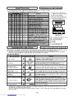
9-2-8. Setting of Remote controller Selector
Switch
When two indoor units are installed in the
separated rooms, there is no need to change
the select switches.
Remote controller Selector Switch
• When two indoor units are installed in the
same room or adjacent two rooms, if operating
a unit, two units may receive the remote
controller signal simultaneously and operate. In
this case, the operation can be preserved by
setting either one indoor unit and remote
controller to B setting
(Both are set to A setting in factory shipment).
• The remote controller signal is not received
when the settings of indoor unit and remote
controller are different.
• There is no relation between A setting/B
setting and A room/B room when connecting
the piping and cables.
1. Setting of remote controller switch at the
indoor unit side
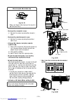
• Remove the front panel.
(1) Before you open the front panel, be sure to
turn off the circuit breaker or the main power
switch.
(2) Open the screw caps and remove the two
screws securing the front cabinet.
(3) Close the screw caps.
(4) Open the vertical air flow louver horizontally by
hand.
(5) Slightly open the lower part of the front cabinet
then pull the upper part of the front cabinet
toward you to remove it from the rear panel.
How to remove the front cabinet
Fig. 9-2-14
2. Put water in the drain pan and make sure that the
water is drained outdoors.
3. When connecting extension drain hose, insulate
the connecting part of extension drain hose with
shield pipe.
Fig. 9-2-15
CAUTION
Arrange the drain pipe for proper drainage from
the unit.
Improper drainage can result in dew-dropping.
9-2-7. Indoor Unit Fixing
1. Pass the pipe through the hole in the wall, and
hook the indoor unit on the installation plate at the
upper hooks.
2. Swing the indoor unit to right and left to confirm
that it is firmly hooked up on the installation plate.
3. While pressing the indoor unit onto the wall by the
lower part, hook it up on the installation plate by
the lower part. Pull the indoor unit toward you by
the lower part to confirm that it is firmly hooked
up on the installation plate.
Fig. 9-2-16
Fig. 9-2-17
50 mm
or more
Do not rise the
drain hose.
Do not form the drain hose
into the waved shape.
Do not put the
drain hose end
into water.
Do not put the drain
hose end in the
drainage ditch.
Shield pipe (local parts)
Extension drain hose
Inside the room
Drain hose
Push
(un-hook)
1 Installation
plate
Hook here
2
Hook
1
(5)
(5)
(2) (3)
Vertical air flow louver
(4)
(2) (3)

