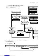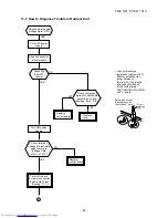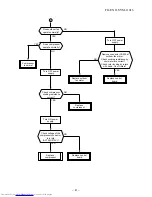
11-7. How to Diagnose Trouble in Outdoor Unit
YES
Turn ON the unit
by remote controller
and wait for 3 min.
Check component
parts of control board
assembly by visual.
(damage, burn,.. Etc.)
Check Power Supply
(Voltage Rate ±10%)
Replace
fuse.
NO
YES
YES
YES
Turn OFF power
supply.
Check 25A
fuse (F01)
failure?
Remove connector
of compressor.
Replace
control board.
Check terminal
Voltage of electrolytic
capacitor are in
(Voltage Rate
Turn ON power
Supply.
NO
±10%) x 1.414?
Replace
control board.
NO
(Cooling : 17°C)
•
Connect discharge
resistance (approx. 100
Ω
,
40W) or soldering iron
(plug) b, –
terminals of the electro-
lytic capacitor (500
µ
F )
of C14 (with printed
CAUTION HIGH VOLTAGE)
on P.C. board.
Discharging position
(Discharging period
10 seconds or more)
Plug of
soldering
iron
FILE NO. SVM-11016
A
–
80
–
Содержание RAS-25SAVP2-ND
Страница 18: ... 17 5 WIRING DIAGRAM FILE NO SVM 11016 ...


