11-4-2 Caution at Servicing
1. After using the service mode of remote controller finished, press the [ ] button to reset the remote controller to
normal function.
2. After finished the diagnosis by the remote controller, turn OFF power supply and turn its ON again to reset the air
conditioner to normal operation. However, the check codes are not deleted from memory of the microcomputer.
3. After servicing finished, press [
CLR
] button of remote controller under service mode status to send code "7F" to the
indoor unit. The check code stored in memory is cleared.
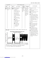
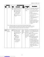
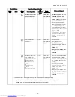
Table 11-4-1
Block distinction
Operation of diagnosis function
Check
code
Block
Check
code
Cause of operation
Air
conditioner
status
Display flashing
error
Indoor P.C.
TA sensor ; The room
Operation
Flashes when
1. Check the sensor TA and connection.
board.
temperature sensor is
continues.
error is detected. 2. In case of the sensor and its
short-Circuit or disconnection.
connection is normal, check the
P.C. board.
TC sensor ; The heat
Operation
Flashes when
1. Check the sensor TC and connection.
exchanger temperature
continues.
error is detected. 2. In case of the sensor and its
sensor of the indoor unit
connection is normal, check the
is out of place, disconnection,
P.C. board.
short-circuit or migration.
Fan motor of the indoor unit
All OFF
Flashes when
1. Check the fan motor and connection.
is failure, lock-rotor, short-
error is detected. 2. In case of the motor and its
circuit, disconnection, etc.
connection is normal, check the
Or its circuit on P.C. board
P.C. board.
has problem.
Other trouble on the indoor
Depend on
Depend on
Replace P.C. board.
P.C. board.
cause of
cause of
failure.
failure.
Action and Judgment
–
68
–
FILE NO. SVM-11016
Содержание RAS-25SAVP2-ND
Страница 18: ... 17 5 WIRING DIAGRAM FILE NO SVM 11016 ...

