–
78
–
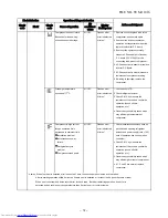
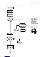
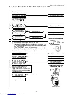
Refer to the chart in 11-6.
Gas leak
P.M.V. is defective.
Miswiring of connecting wires of indoor/outdoor units
Clogging of pipe and coming-off of TC sensor
Gas circulation amount is down.
Measure gas pressure.
Gas shortage
Gas leak
Pipe clogging
Thermo. operation of compressor
Red
White
Terminal block
S5277G
Tester
3
2
1
Terminal block at indoor side
S5277G or equivalent
(Diode with rated voltage of 400V
or more is acceptable.)
To item of Outdoor unit does not operate.
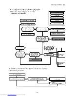
11-5-2. Wiring Failure (Interconnecting and Serial Signal Wire)
(1) Outdoor unit does not operate
1) Is the voltage between
R
and
S
of the indoor terminal block varied?
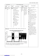
Confirm that transmission from indoor unit to outdoor unit is correctly performed based upon the follow-
ing diagram.
NOTE:
• Measurement should be performed 2 minutes and 30 seconds after starting of the operation.
• Be sure to prepare a diode for judgment.
Normal time
: Voltage swings between DC15 and 60V. ................... Inverter Assembly check (11-8-1.)
Abnormal time : Voltage does not vary.
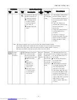
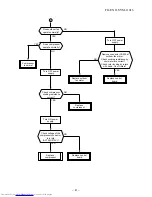
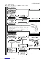
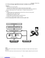
(2) Outdoor unit stops in a little while after operation started
<Check procedure> Select phenomena described below.
1) The outdoor unit stops 10 to 20 minutes after operation started, and 10 minutes or more are required to
restart the unit.
2) If the unit stops once, it does not operate until the power will be turned on again.
3) The outdoor unit stops 10 minutes to 1 hour after operation started, and an alarm is displayed.
(Discharge temp. error check code 03, 1E Sensor temp. error check code 02, 1C)
FILE NO. SVM-11016
Содержание RAS-25SAVP2-ND
Страница 18: ... 17 5 WIRING DIAGRAM FILE NO SVM 11016 ...

