2 Troubleshooting Procedures
2.3 Power Supply Troubleshooting
2.3 Power
Supply
Troubleshooting
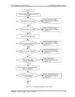
The power supply controls many functions and components. To determine if the power
supply is functioning properly, start with Procedure 1 and continue with the other Procedures
as instructed. The procedures described in this section are:
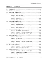
Procedure 1: Icons in the LCD Check
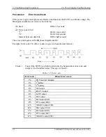
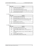
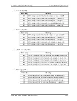
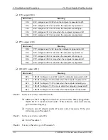
Procedure 2: Error Code Check
Procedure 3: Connection Check
Procedure 4: Charge Check
Procedure 5: Replacement Check
Procedure 1
Icons in the LCD Check
The following Icons in the LCD indicate the power supply status:
Battery icon
DC IN icon
The power supply controller displays the power supply status through the Battery icon and
the DC IN icon in the LCD as listed in the tables below. To check the power supply status,
install a battery pack and connect an AC adaptor.
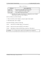
Table 2-1 Battery icon
Battery icon
Power supply status
Lights orange
Battery has been charging and AC adapter is connected.
Lights green
Battery is fully charged and AC adapter is connected.
Blinks orange
(even intervals)
Battery charge is low while system power is ON.
Flashes orange
Battery charge is low. AC adaptor must be connected to recharge the
battery.
Doesn’t light
Any condition other than those above.
2-6
PORTEGE S100 Maintenance Manual (960-508)
Содержание Portege S100 Series
Страница 1: ...Toshiba Personal Computer PORTEGE S100 Maintenance Manual TOSHIBA CORPORATION File Number 960 508 ...
Страница 10: ...x PORTEGE S100 Maintenance Manual 960 508 ...
Страница 11: ...Chapter 1 Hardware Overview ...
Страница 12: ...1 Hardware Overview 1 ii PORTEGE S100 Maintenance Manual 960 508 ...
Страница 25: ...1 2 2 5 inch Hard Disk Drive 1 Hardware Overview PORTEGE S100 Maintenance Manual 960 508 1 11 ...
Страница 36: ...Chapter 2 Troubleshooting Procedures ...
Страница 37: ...2 Troubleshooting Procedures 2 ii PORTEGE S100 Maintenance Manual 960 508 ...
Страница 41: ...2 Troubleshooting Procedures 2 vi PORTEGE S100 Maintenance Manual 960 508 ...
Страница 92: ...Chapter 3 Tests and Diagnostics ...
Страница 93: ...3 Tests and Diagnostics 3 3 ii PORTEGE S100 Maintenance Manual 960 508 ...
Страница 116: ...3 4 Setting of the hardware configuration 3 Tests and Diagnostics PORTEGE S100 Maintenance Manual 960 508 3 19 ...
Страница 199: ...3 31 SETUP 3 Tests and Diagnostics PORTEGE S100 Maintenance Manual 960 508 3 101 ...
Страница 212: ...3 Tests and Diagnostics 3 31 SETUP 3 114 PORTEGE S100 Maintenance Manual 960 508 ...
Страница 213: ...Chapter 4 Replacement Procedures ...
Страница 214: ...4 Replacement Procedures 4 ii PORTEGE S100 Maintenance Manual 960 508 ...
Страница 218: ...4 Replacement Procedures 4 vi PORTEGE S100 Maintenance Manual 960 508 ...
Страница 310: ...4 Replacement Procedure 4 29 Fluorescent Lamp 4 92 PORTEGE S100 Maintenance Manual 960 508 ...
Страница 311: ...Appendices ...
Страница 312: ...Appendices App ii PORTEGE S100 Maintenance Manual 960 508 ...
Страница 318: ...Appendices App viii PORTEGE S100 Maintenance Manual 960 508 ...
Страница 324: ...Appendices Appendix A Handling the LCD Module A 6 PORTEGE S100 Maintenance Manual 960 508 ...
Страница 330: ...Appendices Appendix B Board Layout B 6 PORTEGE S100 Maintenance Manual 960 508 ...
Страница 356: ...Appendices Appendix C Pin Assignments C 26 PORTEGE S100 Maintenance Manual 960 508 ...
Страница 366: ...Appendices Appendix E Key Layout E 2 PORTEGE S100 Maintenance Manual 960 508 ...
Страница 368: ...Appendices Appendix F Wiring diagrams F 2 PORTEGE S100 Maintenance Manual 960 508 ...
Страница 370: ...Appendices Appendix G BIOS rewrite procedures G 2 PORTEGE S100 Maintenance Manual 960 508 ...
Страница 372: ...Appendices Appendix H EC KBC rewrite procedures H 2 PORTEGE S100 Maintenance Manual 960 508 ...
Страница 374: ...Appendices Appendix I Reliability I 2 PORTEGE S100 Maintenance Manual 960 508 ...

