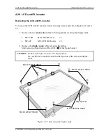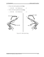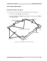
4.26 LCD unit/FL inverter
4 Replacement Procedures
Installing the LCD unit/FL inverter
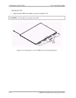
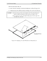
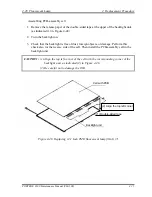
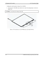
To install the LCD unit/FL inverter, follow the steps below and refer to Figure 4-37 and 4-
38.
1.
Install the
LCD ground plate
to the LCD unit and secure it with the following
screw
.
•
M2
×
3S
S-FLAT HEAD screw
×
1
2.
Connect the
LCD cable
to the LCD unit. Stick the
glass tape
on the LCD cable.
3.
Install the
LCD unit
to the display cover.
4.
Install the
ground wire
and
LCD cable holder
and secure them with the following
screw
.
•
M2
×
3S
S-FLAT HEAD screw
×
1
5.
Connect the two
cables
to the FL inverter and install the
FL inverter
to the display
cover.
6.
Stick the
insulator
on the FL inverter and put the other
insulator
under the LCD
unit.
7.
Install the
display mask
while hooking the latches.
CAUTION:
Double-sided tape is stuck to the display mask.
Be careful not to touch the double-sided tape portion of the display mask,
when installing.
8.
Secure the display mask with the following
screws
.
•
M2.5
×
6B
FLAT HEAD screw
×
2
•
M2
×
4C
S-FLAT HEAD screw
×
8
9.
Stick the ten
mask seals
.
PORTEGE S100 Maintenance Manual (960-508)
4-61
Содержание Portege S100 Series
Страница 1: ...Toshiba Personal Computer PORTEGE S100 Maintenance Manual TOSHIBA CORPORATION File Number 960 508 ...
Страница 10: ...x PORTEGE S100 Maintenance Manual 960 508 ...
Страница 11: ...Chapter 1 Hardware Overview ...
Страница 12: ...1 Hardware Overview 1 ii PORTEGE S100 Maintenance Manual 960 508 ...
Страница 25: ...1 2 2 5 inch Hard Disk Drive 1 Hardware Overview PORTEGE S100 Maintenance Manual 960 508 1 11 ...
Страница 36: ...Chapter 2 Troubleshooting Procedures ...
Страница 37: ...2 Troubleshooting Procedures 2 ii PORTEGE S100 Maintenance Manual 960 508 ...
Страница 41: ...2 Troubleshooting Procedures 2 vi PORTEGE S100 Maintenance Manual 960 508 ...
Страница 92: ...Chapter 3 Tests and Diagnostics ...
Страница 93: ...3 Tests and Diagnostics 3 3 ii PORTEGE S100 Maintenance Manual 960 508 ...
Страница 116: ...3 4 Setting of the hardware configuration 3 Tests and Diagnostics PORTEGE S100 Maintenance Manual 960 508 3 19 ...
Страница 199: ...3 31 SETUP 3 Tests and Diagnostics PORTEGE S100 Maintenance Manual 960 508 3 101 ...
Страница 212: ...3 Tests and Diagnostics 3 31 SETUP 3 114 PORTEGE S100 Maintenance Manual 960 508 ...
Страница 213: ...Chapter 4 Replacement Procedures ...
Страница 214: ...4 Replacement Procedures 4 ii PORTEGE S100 Maintenance Manual 960 508 ...
Страница 218: ...4 Replacement Procedures 4 vi PORTEGE S100 Maintenance Manual 960 508 ...
Страница 310: ...4 Replacement Procedure 4 29 Fluorescent Lamp 4 92 PORTEGE S100 Maintenance Manual 960 508 ...
Страница 311: ...Appendices ...
Страница 312: ...Appendices App ii PORTEGE S100 Maintenance Manual 960 508 ...
Страница 318: ...Appendices App viii PORTEGE S100 Maintenance Manual 960 508 ...
Страница 324: ...Appendices Appendix A Handling the LCD Module A 6 PORTEGE S100 Maintenance Manual 960 508 ...
Страница 330: ...Appendices Appendix B Board Layout B 6 PORTEGE S100 Maintenance Manual 960 508 ...
Страница 356: ...Appendices Appendix C Pin Assignments C 26 PORTEGE S100 Maintenance Manual 960 508 ...
Страница 366: ...Appendices Appendix E Key Layout E 2 PORTEGE S100 Maintenance Manual 960 508 ...
Страница 368: ...Appendices Appendix F Wiring diagrams F 2 PORTEGE S100 Maintenance Manual 960 508 ...
Страница 370: ...Appendices Appendix G BIOS rewrite procedures G 2 PORTEGE S100 Maintenance Manual 960 508 ...
Страница 372: ...Appendices Appendix H EC KBC rewrite procedures H 2 PORTEGE S100 Maintenance Manual 960 508 ...
Страница 374: ...Appendices Appendix I Reliability I 2 PORTEGE S100 Maintenance Manual 960 508 ...


