


DISASSEMBLY INSTRUCTIONS
B1-1
TV PCB Holder
Main PCB
1
Main PCB Holder
VCR Block
3
2 2
4
Front Cabinet
TV/VCR Block
2
UP TO
RELEASE
1
1
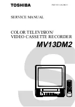
Remove the Anode Cap.
(Refer to REMOVAL OF ANODE CAP)
Disconnect the following connectors:
(CP801 and CP850).
Remove the CRT PCB in the direction of arrow.
REMOVAL OF MECHANICAL PARTS
AND P.C. BOARDS
CAUTION: BEFORE REMOVING THE ANODE CAP,
DISCHARGE ELECTRICITY BECAUSE IT
CONTAINS HIGH VOLTAGE.
BEFORE ATTEMPTING TO REMOVE OR
REPAIR ANY PCB, UNPLUG THE POWER
CORD FROM THE AC SOURCE.
CRT PCB
Front Cabinet
Fig. 1-2
1.
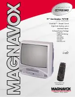
1-1: BACK CABINET (Refer to Fig. 1-1)
1.
2.
3.
4.
Remove the 4 screws
1
.
Remove the 3 screws
2
which are used for holding the
Back Cabinet.
Remove the AC cord from the AC cord hook
3
.
Remove the Back Cabinet in the direction of arrow.
Fig. 1-1
Front Cabinet
1-2: CRT PCB (Refer to Fig. 1-2)
1.
2.
3.
1-3: TV/VCR BLOCK (Refer to Fig. 1-3)
1.
2.
3.
4.
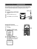
1-4: MAIN PCB (Refer to Fig. 1-4)
1.
2.
3.
4.
5.
6.
7.
8.
Remove the screw
1
.
Remove the Main PCB Holder.
Remove the 2 screws
2
.
Remove the 3 screws
3
.
Remove the screw
4
.
Remove the TV PCB Holder.
Disconnect the following connectors:
(CP402, CD502, CP502 and CP820).
Remove the Main PCB in the direction of arrow.
Remove the 2 screws
1
.
Disconnect the following connectors:
(CP401, CP403, CP503 and CP304).
Unlock the support
2
.
Remove the TV/VCR Block in the direction of arrow.
Back Cabinet
Fig. 1-4
1
1
2
2
2
3
1
1
Fig. 1-3