– 64 –
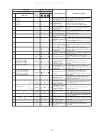
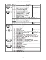
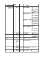
Main
remote
control
Check code
L09
—
—
Indoor
unit
Indoor capacity
not set
Stop of
corresponding
unit
Capacity setting has not been
performed for indoor unit.
Set indoor capacity. (DN = 11)
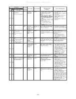
L10
L10
—
I/F
Outdoor
capacity not set
All stop
Jumper wire provided on P.C.
board for servicing I/F P.C. board
has not been removed as required
for given model.
Check model setting of P.C. board
for servicing outdoor I/F P.C. board.
L20
—
—
Network
adaptor
Indoor unit
Duplicated
central control
address
All stop
There is duplication in central
control address setting.
• Check central control addresses.
• Check network adaptor P.C.
board .
L23
—
—
I/F
SW setting
mistake
All stop
Outdoor P.C. board (I/F) does not
operate normally.
• Check switch setting of Bit 3 and
4 of SW17 in outdoor P.C. board
(I/F).
L28
L28
—
I/F
Too many
outdoor units
connected
All stop
There are more than three outdoor
units.
• Check No. of outdoor units
connected (Only up to 3 units per
system allowed).
• Check communication lines
between outdoor units.
• Check for defect in outdoor P.C.
board (I/F).
—
L31
—
I/F
Extended IC
trouble
Continued
operation
There is part failure in P.C. board
(I/F).
Check outdoor P.C. board
(I/F).
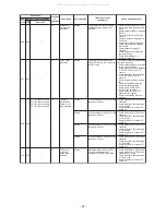
P01
—
—
Indoor
unit
Indoor fan
motor trouble
Stop of
corresponding
unit
• Check the lock of fan motor
(AC fan).
• Check wiring.
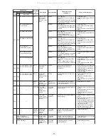
L30
L30
Detected indoor
address
Indoor
unit
External
interlock of
indoor unit
Stop of
corresponding
unit
• Signal is present at external
trouble input terminal (CN80)
for 1 minute.
When external device is
connected to CN80 connector:
1) Check for defect in external
device.
2) Check for defect in indoor P.C.
board.
When external device is not
connected to CN80 connector:
1) Check for defect in indoor P.C.
board.
L29
L29
I/F
Trouble in No.
of IPDUs
All stop
Insufficient number of IPDUs are
detected when power is turned on.
• Check model setting of P.C.
board for servicing outdoor I/F
P.C. board.
• Check connection of UART
communication connector.
• Check A3-IPDU, fan IPDU, and
I/F P.C. board for defect.
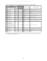
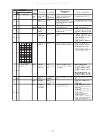
Outdoor 7-segment display
Check
code
Sub-code
Location
of
detection
Description
System status
Trouble detection
condition(s)
Check items (locations)
A3-IPDU
Circle (O): IPDU trouble
Fan-IPDU
1
O
O
O
O
O
O
O
O
01
02
03
08
09
0A
0B
10
11
12
13
18
19
1A
1B
2
O
O
O
O
O
O
O
O
1
O
O
O
O
O
O
O
O
2
O
O
O
O
O
O
O
O
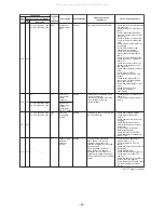
P03
P03
—
I/F
Discharge
temperature
TD1 trouble
All stop
Discharge temperature (TD1)
exceeds 239°F (115°C).
• Check outdoor service valves
(gas side, liquid side) to confirm
full opening.
• Check outdoor PMVs (PMV1, 3)
for clogging.
• Check resistance characteristics
of TD1 sensor.
• Check for insufficiency in
refrigerant quantity.
• Check for defect in 4-way valve.
• Check for leakage of SV4 circuit.
• Check SV4 circuit (wiring or
installation trouble in SV41 or SV42).
All manuals and user guides at all-guides.com


