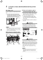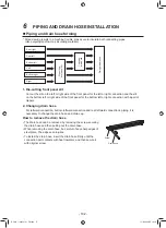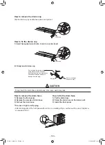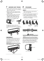
9
REFRIGERANT PIPING
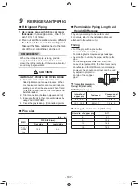
Refrigerant Piping
1.
Use copper pipe with 0.8 mm or more
thickness.
(In case pipe size is dia. 15.9,
with 1.0 mm or more.)
2. Flare nut and
fl
are works are also different
from those of the conventional refrigerant.
Take out the
fl
are nut attached to the main
unit of the air conditioner, and use it.
REQUIREMENT
When the refrigerant pipe is long, provide
support brackets at intervals of 2.5 to 3 m to
clamp the refrigerant pipe. Otherwise, abnormal
sound may be generated.
CAUTION
IMPORTANT 4 POINTS FOR PIPING WORK
1. Reusable mechanical connectors and
flared joints are not allowed indoors. When
mechanical connectors are reused indoors,
sealing parts shall be renewed. When flared
joints are reused indoors, the flare part shall
be refabricated.
2. Tight connection (between pipes and unit)
3. Evacuate the air in the connecting pipes by
using VACUUM PUMP.
4. Check the gas leakage. (Connected points)
Pipe size
(dia. : mm)
MMK-
PIPE SIZE (mm)
Gas side
Liquid side
UP027 to
UP036
type
15.9
9.5
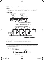
Permissible Piping Length and
Height Difference
They vary according to the outdoor unit.
For details, refer to the Installation Manual
attached to the outdoor unit.
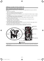
Flaring
෬
Cut the pipe with a pipe cutter.
Remove burrs completely.
Remaining burrs may cause gas leakage.
෬
Insert a
fl
are nut into the pipe, and
fl
are the
pipe.
As
the
fl
aring sizes of R410A differ from
those of refrigerant R22, the
fl
are tools newly
manufactured for R410A are recommended.
However, the conventional tools can be used
by adjusting projection
margin of the copper
pipe.
T
Projection margin in
flaring: B (Unit: mm)
RIDGID
(Clutch type)
Outer dia. of
copper pipe
Tool used
Conventional
tool used
6.4 , 9.5
0.5 to 1.0
1.0 to 1.5
12.7 , 15.9
0.5 to 1.1
1.5 to 2.0
T
Flaring dia. meter size: A (Unit: mm)
Outer dia. of copper pipe
A
+0
-0.4
6.4
9.1
9.5
13.2
12.7
16.6
15.9
19.7
B
BOOK_1130550101_EN.indd 22
BOOK_1130550101_EN.indd 22
11/2/2564 BE 19:18
11/2/2564 BE 19:18
- 107 -


