Basic Installation and Operation Guide
JK 400 Series Fixed Controllers
TOSHIBA
23
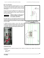
Main Bus Compartment
Main bus bars extending horizontally throughout a line
-up are
located in an isolated compartment located in the rear center of
the
enclosure (Fig. 3
6a & 36b
). From the main bus, riser bars
supply power to the controller. Standard main bus bars are copper
with tin plating.
Access to the main bus compartment can be obtained either by
removing the enclosure back sheet or by swinging open the
hinged low voltage subpanel and then removing a fixed barrier
that covers the main bus.
Hazardous Voltage. Turn off and lock out
all control and primary power before
accessing this compartment.
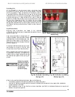
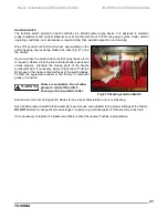
Bus splice links (
Fig. 37)
are furnished for joining the main bus
and ground bus between shipping sections. With the low voltage
subpanel swung open and the main bus barrier removed, all splice
links can be installed from the front of the unit. Refer to Installation
Section for details.
Fig. 36a Main Bus (1200A & 2000A)
Compartment
A copper ground bus, located in front of the main bus
compartment and above the isolation switch, is used to provide a
common ground between cubicles. The ground bus also provides
a termination point for grounding the enclosure and for
connecting the ground wires from shielded cable terminators.
Fig. 37 Bus Splice Links
Fig. 36b Main Bus (3000A) Compartment
PREPARED SPACES
Prepared spaces are compartments equipped for future addition of controllers and are supplied with the following
components:
- Isolation Switch
- Riser bus
DANGER
Содержание JK400 Series
Страница 2: ...Basic Installation and Operation Guide JK Series 400 Series Fixed Controllers ...
Страница 9: ...Basic Installation and Operation Guide JK 400 Series Fixed Controllers TOSHIBA ...
Страница 46: ......
Страница 47: ......

