GD-1300 FAX SOFT SWITCH 5 - 32
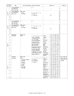
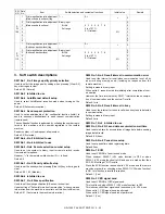
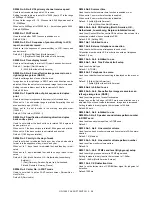
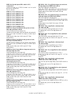
SW91 No.8 Symbol speed 2743 enable in V.34
communicate
Used to set whether use of 2743Hz is allowed or not as symbol
speed in V.34 communicate.
Default: 1 (Enable)
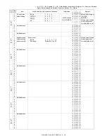
SW92 No.1–No.8 Inhibited to use
SW93 No.1–No.8 Inhibited to use
SW94 No.1–No.8 Inhibited to use
SW95 No.1–No.8 Inhibited to use
SW96 No.1–No.8 Inhibited to use
SW97 No.1–No.8 Inhibited to use
SW98 No.1–No.8 Inhibited to use
SW99 No.1–No.8 Inhibited to use
SW100 No.1–No.8 Inhibited to use
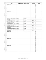
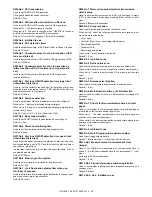
SW101 No.1–No.4 Print effective image area sub scan
lead edge void (Back surface)
Used to set void amount in print image area.
Void amount on the lead edge in sub scan direction can be adjusted.
When the set value is increased, the margin on the lead edge is
increased.
Setting is made in binary input in the increment of 16 lines.
Default: 32 lines
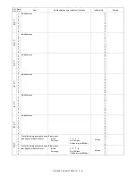
SW101 No.5–No.8 Print effective image area sub scan
rear edge void (Back surface)
Void amount on the rear edge in sub scan direction can be adjusted.
When the set value is increased, the margin on the read edge is
increased.
Setting is made in binary input in the increment of 16 lines.
Default: 48 lines
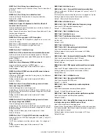
SW102 No.1–No.4 Scan effective image area main scan
left edge image loss (OC)
Used to set image loss in scan image area.
Image loss on the left edge in OC main scan direction can be
adjusted. When the set value is increased, image loss is increased.
Setting is made in binary input in the increment of 24 dots.
Default: 96 dots
SW102 No.5–No.8 Scan effective image area main scan
right edge image loss (OC)
Used to set image loss in scan image area.
Image loss on the right edge in OC main scan direction can be
adjusted. When the set value is increased, image loss is increased.
Setting is made in binary input in the increment of 24 dots.
Default: 96 dots
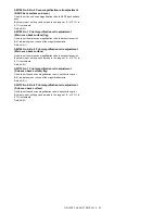
SW103 No.1–No.4 Scan effective image area sub scan
lead edge image loss (OC)
Used to set image loss in scan image area.
Image loss on the lead edge in OC sub scan direction can be
adjusted. When the set value is increased, image loss is increased.
Setting is made in binary input in the increment of 16 lines.
Default: 96 lines
SW103 No.5–No.8 Scan effective image area sub scan
rear edge image loss (OC)
Used to set image loss in scan image area.
Image loss on the rear edge in OC sub scan direction can be
adjusted. When the set value is increased, image loss is increased.
Setting is made in binary input in the increment of 16 lines.
Default: 144 lines
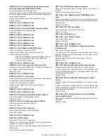
SW104 No.1–No.4 Scan effective image area main scan
left edge image loss (RADF back surface)
Used to set image loss in scan image area.
Image loss in RADF back surface main scan direction can be
adjusted. When the set value is increased, image loss is increased.
Setting is made in binary input in the increment of 24 dots.
Default: 96 dots
SW104 No.5–No.8 Scan effective image area main scan
right edge image loss (RADF back surface)
Used to set image loss in scan image area.
Image loss on the right edge in RADF back surface main scan direc-
tion can be adjusted. When the set value is increased, image loss is
increased.
Setting is made in binary input in the increment of 24 dots.
Default: 96 dots
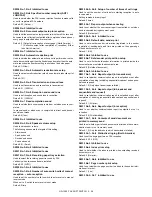
SW105 No.1 Scan magnification ratio adjustment
(OC main scan) flag
Used to set the main scan magnification ratio in OC scan.
Bit 1 indicates plus or minus of the magnification ratio.
Default: 0 (+)
SW105 No.2–No.8 Scan magnification ratio adjustment
(OC main scan)
Used to set the main scan magnification ratio in OC scan.
By binary input, setting can be made in the range of 0 – ±12.7% in
0.1% increments.
Default: 0%
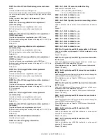
SW106 No.1 Scan magnification ratio adjustment
(OC sub scan) flag
Used to set the sub scan magnification ratio in OC scan.
Bit 1 indicates plus or minus of the magnification ratio.
Default: 0 (+)
SW106 No.2–No.8 Scan magnification ratio adjustment
(OC sub scan)
Used to set the sub scan magnification ratio in OC scan.
By binary input, setting can be made in the range of 0 – ±12.7% in
0.1% increments.
Default: 0%
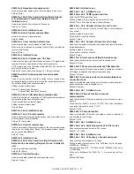
SW107 No.1 Scan magnification ratio adjustment
(RADF back surface main scan) flag
Used to set the main scan magnification ratio in RADF back surface
scan.
Bit 1 indicates plus or minus of the magnification ratio.
Default: 0 (+)
SW107 No.2–No.8 Scan magnification ratio adjustment
(RADF back surface main scan)
Used to set the main scan magnification ratio in RADF back surface
scan.
By binary input, setting can be made in the range of 0 – ±12.7% in
0.1% increments.
Default: 0%
SW108 No.1 Scan magnification ratio adjustment
(RADF back surface sub scan) flag
Used to set the sub scan magnification ratio in RADF back surface
scan.
Bit 1 indicates plus or minus of the magnification ratio.
Default: 0 (+)

