GD-1300 INSTALLATION PROCEDURE 3 - 2
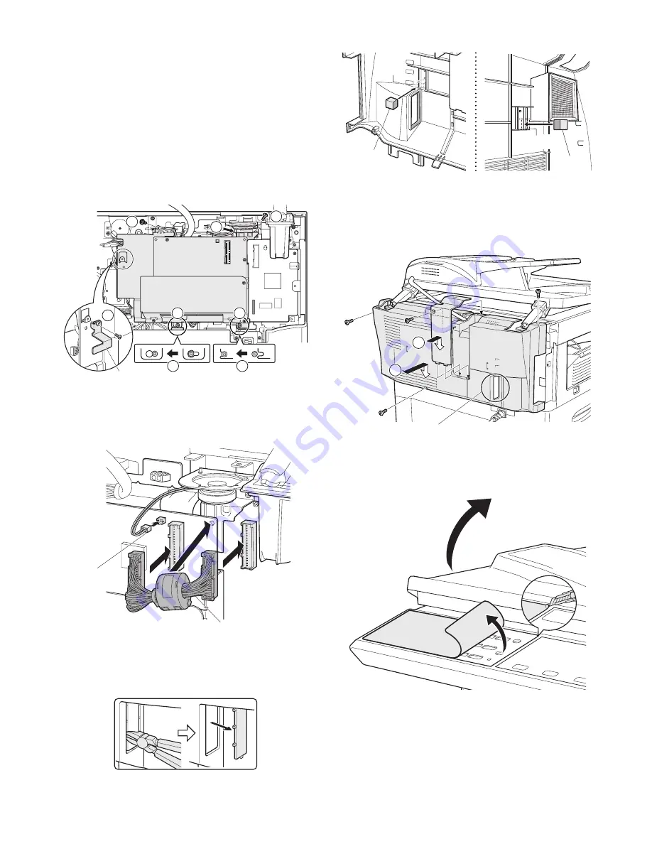
4) Align the top frame portion of the FAX modem PWB with the
screw hole at the back of the speaker unit.
5) Place the holes of the bottom portion of the FAX modem PWB
onto the loosely tightened screws.
Slide the PWB to left to secure as shown below.
6) When RADF is installed, secure the RADF ground terminal
and the FAX modem PWB onto the copier using the screw
removed earlier in (4)-1).
• When OC is installed, secure the FAX modem PWB onto
the copier using a supplied screw.
7) Secure the FAX modem PWB onto the copier using a supplied
screw.
8) Tighten two loosely tightened screws completely.
9) Secure the ground angle using a supplied screw.
(5) Connect the cable, and the speaker connector
Connect the copier and the FAX modem PWB with the cable.
Fix the snap band to the FAX PWB.
NOTE: Connect the speaker connector to the FAX modem PWB.
(6) Work the rear cabinet, and attach the gasket.
1) Cut and remove the cut-out portion from the rear cabinet using
a tool such as nippers. (Be careful with the tool’s direction so
that the cut surface is flat.)
2) Attach two Gasket as shown.
(7) Reattach the rear cabinet.
1) Reattach the rear cabinet and secure it using three screws.
2) Reattach the rear cabinet shielding plate and secure it using
one screw removed earlier.
Reattach the RADF detached in Step (1).
(8) Peel off the dummy key sheet.
Open the RADF or OC.
Peel the edge of the dummy key sheet using a tool such as a
retractable knife, and then peel off the entire key sheet.
Ground angle
6
4
7
8
9
5
5
8
Speaker
connector
Cable
Gasket
Gasket
Putting
standard
Putting
standard
1
2
Cut-out portion


