background image

January 2001 © TOSHIBA TEC

2 - 9

GD-1060  SPECIFICATIONSACCESSORIESOPTIONS

(1) Discard printing

Func. 15 bit 2 permits selecting between ON and OFF of the option for discard extra.

Func. 15 bit 2 = 0 : OFF

Func. 15 bit 2 = 1 : ON (Default)

Func. 15 bits 6 and 7 allow the discard parameter to be set.

Func. 15 (Default Setting bit 2 = 0, bit 6 = 1, bit 7 = 0)

bit 2

bit 6

bit 7

Discard parameter

0

X

X

Discard OFF

1

0

0

0 mm (Discard OFF)

1

1

0

10 mm

1

0

1

17 mm

1

1

1

34 mm

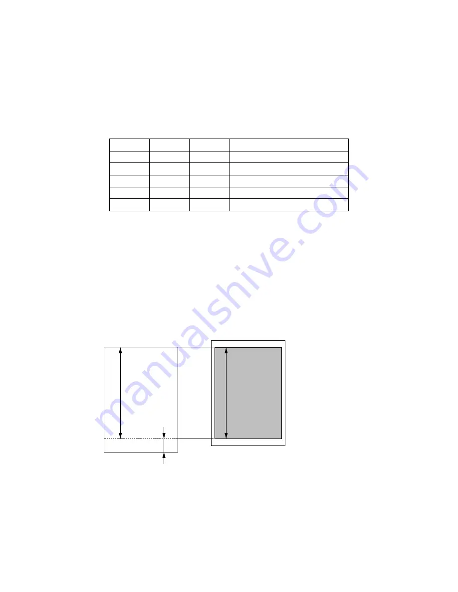
When the option for discard extra is ON:

When the length of the received document in the feed direction exceeds the effective recording

area and the part exceeding one page is within the discard parameter, printing takes place with

the exceeding part discarded. When the length of the received document in the feed direction

exceeds the discard parameter range and is within the reduction range of the maximum reduce

ratio, vertical reduction print takes place. When it is not within the reduction range of the maxi-

mum reduce ratio, divided print takes place. The discard extra takes preference over the vertical

reduction print.

When the option for discard extra is OFF:

The vertical reduction takes preference without performing discard extra print.

Rcv. doc.

Rcd. paper

A

B

A

A: Effective recording area

B: Record data length outside

effective recording area

If the length of B is less than the set discard parameter, B is discarded.

Содержание GD-1060

Страница 1: ...Click the Bookmarks to open the Contents and display Bookmarks created for the document Click a bookmark s name to go to the Page marked by that bookmark Click the Thumbnails to open the overview area and display thumbnail images of each document page Click a thumbnail to go to the Page marked by that thumbnail SERVICE MANUAL FACSIMILE FORDP1600 2000 2500 GD 1060 ...

Страница 2: ...irect sunlight Also provide proper ventilation as the copier emits a slight amount of ozone To insure adequate working space for the copying operation keep a minimum clearance of 80 cm 32 on the left 80 cm 32 on the right and 10 cm 4 in the rear After having installed the copier be sure to push the carrying handles into the copier 3 Service of Machines Basically be sure to turn the main switch off...

Страница 3: ... relevant local regulations or rules 7 When parts are disassembled reassembly is basically the reverse of disas sembly unless otherwise noted in this manual or other related documents Be careful not to reassemble small parts such as screws washers pins E rings toothed washers in the wrong places 8 Basically the machine should not be operated with any parts removed or dis assembled 9 Precautions Ag...

Страница 4: ...DP1600 2000 2500 1 FORM OF FAX OPTIONS OF DP1600 2000 2500 1 1 Fax Options Necessary options to install the fax unit Several options can be supplied which are necessary for extension to extend the box function when you install the fax unit Refer to 2 4 in detail ...

Страница 5: ...r NAD model Horizontal scanning Max 280 mm Ledger width Vertical scanning Max 1000 mm For MJD AUD ASD SAD TWD and CND models Horizontal scanning Max 297 mm A3 width Vertical scanning Max 1000 mm Note The maximum vertical scanning length is 700 mm when transmission is performed satisfying all of the following conditions The copier is in the long original mode Direct transmission is performed The or...

Страница 6: ...d sheets and stapled sheets Max size A3 LD Capacity of originals For NAD model LT LT R ST R LG Comp LD 50 sheets with ADF LT LT R ST R LG Comp LD 100 sheets with RADF For MJD AUD ASD SAD TWD and CND models A4 A4 R B5 B5 R A5 R B4 Folio A3 50 sheets with ADF A4 A4 R B5 B5 R A5 R B4 Folio A3 100 sheets with RADF 2 1 2 Transmission system Line used Telephone line Communication mode Exclusive mode CRP...

Страница 7: ...R 14 4K 12 0K 9 6K 7 2K 4 8K 2 4K 300 bps V 21 Conforming to T 30 ECM 8 dots mm 16 dots mm 3 85 lines mm 7 7 lines mm 15 4 lines mm MH MR MMR JBIG 14 4K 12 0K 9 6K 7 2K 4 8K 2 4K 33 6K 31 2K 28 8K 26 4K 24 0K 21 6K 19 2K 16 8K 14 4K 12 0K 9 6K 7 2K 4 8K 2 4K 1200 bps V 34 300 bps V 21 Conforming to T 30 2 1 3 Telephone functions Dial line function Pulse method 10 pps DTMF method On Off hook dial f...

Страница 8: ...e performance Table Item Maximum address numbers of diabl Memory capability Maximum numbers of Sub Item Keypad dial Abbreviated dial Alphabet dial One touch dial Multi address group Multi address using MULTI key ITU T Mailbox Relay box Chain dial Maximum number of dialing Transmission pix memory Memory reception pix memory Tx reservation jobs Numbers of page at 1 memory Tx Limitation 128 digits 30...

Страница 9: ...2 2 Effective recording area a Head 4 mm 0 16 inch b Foot 4 mm 0 16 inch c Effective Recording Limits 1 For NAD model Unit mm inch Paper size Size Horizontal x Vertical Effective recording area LD 279 x 432 275 x 424 11 x 17 10 8 x 16 7 LG 216 x 356 212 x 348 8 5 x 14 8 3 x 13 7 LT 279 x 216 275 x 208 11 x 8 5 10 8 x 8 2 LT R 216 x 279 212 x 271 8 5 x 11 8 3 x 10 7 ST R 140 x 216 136 x 208 5 5 x 8...

Страница 10: ...ive recording range A3 297 x 420 293 x 412 A4 297 x 210 293 x 202 A4 R 210 x 297 206 x 289 A5 R 148 x 210 144 x 202 B4 257 x 364 253 x 356 FOLIO 210 x 330 206 x 322 LT 279 x 216 275 x 208 11 x 8 5 10 8 x 8 2 LT R 216 x 279 212 x 271 8 5 x 11 8 3 x 10 7 Fig 2 2 1 2 mm 0 08 inch Effective recording area Feed direction 4 mm 0 16 inch 02 02 01 2 mm 0 08 inch 4 mm 0 16 inch ...

Страница 11: ...as a rule If no recording paper of the identified size is not available it selects recording paper for printing according to the set mode The mode is set by using Func 15 bit 3 1 Automatic reduction mode Func 15 bit 3 0 Default Selects recording paper on which the received document can be printed and prints on it 2 Reduction OFF mode Func 15 bit 3 1 Selects recording paper on which the received do...

Страница 12: ...ser Vertical reduction Function setting by user Discard parameter Func 15 bit 6 7 Reception print flowchart Vertical reduction print Divided print Start YES YES Full size print Fraction discard print Receive FAX Within effective recording area NO Fraction discard ON Within fraction discard length range Vertical reduction ON γ within max reduce ratio Calculate reduce ratio γ from actual image data ...

Страница 13: ... and the part exceeding one page is within the discard parameter printing takes place with the exceeding part discarded When the length of the received document in the feed direction exceeds the discard parameter range and is within the reduction range of the maximum reduce ratio vertical reduction print takes place When it is not within the reduction range of the maxi mum reduce ratio divided pri...

Страница 14: ...tio 73 The reduce ratio settings of 95 90 86 80 83 and 73 are valid When the option for vertical reduction print is OFF When the length of the received document in the feed direction exceeds the effective recording area divided print takes place 3 Divided print When received data cannot be recorded on one sheet even if reception reduction and reception discard are carried out the recorded data is ...

Страница 15: ...tion function is performed after discard extra reduction or dividing processing The rotation function is valid for received documents of A4 LT A5 and ST R sizes 6 Printing with no recording paper When recording paper has run out during printing printing takes place on another printable re cording paper starting from the next page if available However if recording paper has run out in the middle of...

Страница 16: ...nted on each page but RTI is printed on the first page only in the case of divided print ON or OFF of RTI is possible by means of the user setting Default OFF RTI is created for the LT or A4 R width When printing RTI on A5 B5 and ST R smaller than those sheets the information to be printed is reduced to a printable length LT size or up A5 B5 ST R ...

Страница 17: ...to be printed on one page with a max reduce ratio of 75 is selected The recording paper length of A4 is 297 mm the recording paper length of B4 is 364 mm and the recording paper length of A3 is 420 mm Therefore an A3 paper range covering 390 mm is selected After an A3 range is selected record ing paper is selected according to the priority in Table 2 2 1 followed by printing Recording paper range ...

Страница 18: ...aper For NAD model For MJD AUD ASD SAD TWD and CND models Recording paper range A4 R B4 A3 A4 A5 FOLIO B5 1 A4 R B4 A3 A4 A5 R 3 FOLIO B4 2 A4 3 A3 2 B4 1 A4 R 3 A4 R B4 2 A4 2 3 FOLIO A4 R 1 A4 R 1 A3 A4 3 A3 2 A4 R 2 3 4 LT R A4 1 3 A4 1 3 FOLIO 2 3 FOLIO A4 R A3 2 3 5 LT 3 FOLIO 1 FOLIO 1 B4 2 3 LT R A4 3 FOLIO 2 3 6 B4 2 LT R 1 LT R 1 LT LT 3 LT R LT 2 7 A3 2 LT 1 3 LT 1 3 LT R 3 B4 2 LT 3 LT ...

Страница 19: ...2 Selection of recording paper Long original For NAD model For MJD AUD ASD SAD TWD and CND models 1 Similar reduction possible 2 Center printing when printing out to a size larger in the scanning direction 3 Rotation processing Priority of recording paper Recording paper range A4 long B4 long A3 long 1 A3 2 A3 2 A3 2 B4 2 B4 B4 1 3 A4 R A4 R 1 A4 R 1 4 A4 3 A4 1 3 A4 1 3 5 FOLIO FOLIO 1 FOLIO 1 6 ...

Страница 20: ...formed from the SFB 2 When the JSP is installed reception print is always performed from the upper cassette After the upper tray becomes full memory reception is performed When the lower tray becomes full printing of received facsimile is possible 3 Even if the OCT is installed it cannot be used during reception print 4 When the finisher is installed it cannot be used 5 Even if the ADU is installe...

Страница 21: ...nel 1 pc Fax panel bottom cover 1 pc Fax PWA 1 pc NCU PWA 1 pc Battery 1 pc Fax panel harness 1 pc Ground wire 1 pc Locking support 1 pc Band 2 pcs BAIND screw M 3x8 4 pcs PAN Head screw M 3x8 2 pcs 1 The label that differs according to destination is packed Accessory name Q ty Operator s manual for facsimile function 1 pc Installation procedures 1 pc TEL LINE cable 1 pc SUPER G3 label 1 pc T A la...

Страница 22: ...led under the copier MY 1015N MY 1015N PFP Paper feed pedestal KD 1009 KD 1009 3rd CASSETTE A cassette which can be installed under the PFU KD 1009N KD 1009N CM Cassette module MY 1017 4th CASSETTE The cassette module which can be installed MY 1017N in the PFP LCF Large capacity feeder KD 1010 Large capacity feeder for A4 or LETTER size which can be installed under the PFU 2 4 Options Extends the ...

Страница 23: ...er ADF MR 2012 MR 2012N Original cover KA 1600PC Fax board kit GD 1060 NA EU AU TW FAX board NCU board Operation panel Large capacity feeder LCF KD 1010 for DP2000 2500 series DP1600 2000 2500 Paper feed unit PFU MY 1015 MY 1015N Cassette mdule CM MY 1017 MY 1017N for DP2000 2500 series Paper feed pedestal PFP KD 1009 KD 1009N 2 5 System List ...

Страница 24: ...ximum office productivity and efficiency Patterns of the multi access are as follows 1 Scan to Memory during Memory Transmission 2 Scan to Memory during Reception 3 Scan to Memory during Substitute Reception 4 Copying during Memory Transmission 5 Reception during Copying 6 Reception during Memory printing 7 Reception during List printing 8 Scan to Memory during Memory printing 9 Scan to Memory dur...

Страница 25: ...ne abbreviated dial number or one touch dial key one as the primary telephone number and the other as an alternate telephone number The facsimile first dials the primary telephone number then redials if the line is busy until the redialing limit count is reached It will then begin to dial the alternate number Except for Relay Mailbox Confidential Polling Multi address transmission function Transmi...

Страница 26: ... the designated day of week Sub address communication The GD 1060 NA TW AU EU supports communication applications using sub address SUB SEP PWD commands conforming to ITU T Sub address communication is possible by keypad dialing one touch key dialing and abbreviated dialing using the sub address settings in Comm Options Security communication For transmissions the facsimile checks if the telephone...

Страница 27: ...such as a company logo to be included Account code By entering a different account code for each destination at the time of transmission account codes will identify when for whom and to whom a particular facsimile message was sent Department code Permits assigning 99 department codes to control access and track activity These codes are set up beforehand and must be used to access machine functions...

Страница 28: ...s not expected The fast warm up time ensures the printer section will be ready before a full page of image data can be received Recovery transmission Originals that have gone through the redial count limit will not be cleared but stored for a programmed period of time Such originals can be recovered to be transmitted again F code mailbox relay box communication Bulletin board F code mailbox transm...

Страница 29: ...60 GENERAL 3 6 January 2001 TOSHIBA TEC 3 2 Overview 3 2 1 Front view Fig 3 2 1 03 02 01 Receiving tray Control panel Recording paper cassette Power switch Original glass ADF glass Original scale Front cover ...

Страница 30: ...January 2001 TOSHIBA TEC 3 7 GD 1060 GENERAL 3 2 2 Rear view Side cover Line connector LINE External telephone connector TEL GD 1060 NA TW models Not used Fig 3 2 2 03 02 02 ...

Страница 31: ...ode 3 RESOLUTION key Selects the desired resolution for transmission A selected resolution is shown on the LCD 4 MONITOR key Used to enable the speaker monitor for monitoring call progress during non memory original feeder transmission 5 REDIAL PAUSE key Press this key to redial a facsimile telephone number if the number was busy on your first try Or use this key to enter a pause between telephone...

Страница 32: ... key to switch from the other modes to the COPY mode Please refer to the Operator s Manual for Copying Function for further information about the settings and operation in the COPY mode 9 Paper Jam Lamp This lamp blinks when an original or recording paper is jammed 10 Recording Paper Lamp Used to accessing Abbreviated Alphabet or Group dialing telephone directories This lamp blinks in the FAX mode...

Страница 33: ...ne is in the PRINTER mode 16 MAIN MENU key and MAIN MENU lamp Press this key to switch from the PROGRAM mode to the MAIN MENU COPY SCAN FAX or PRINTER mode Illuminated when the machine is in the MAIN MENU 17 PROGRAM key and PROGRAM lamp Use this key to reset the settings of the copier or the default settings Illuminated when the machine is in the PROGRAM mode 18 INTERRUPT key and INTERRUPT lamp Th...

Страница 34: ...he PROGRAM mode or Added Feature 25 CANCEL key Use this key to return to a previous menu in the PROGRAM mode or COMM option 26 IMAGE MODE key and IMAGE MODE Lamps Selects the desired image mode TEXT TEXT PHOTO and PHOTO for transmission A selected image mode lamp is illuminated 27 FINISHING key This key is not used in the FAX mode 28 ZOOM key This key is not used in the FAX mode 29 PAPER SUPPLY ke...

Страница 35: ...l and One Touch Dial programming DELAYED COMM Schedules a delayed communication job to be performed at a designated time DIRECTTX Allows transmission direct from the original glass or the optional document feeder without the use of memory LOW SPEEDTX Used to select a lower transmission speed to transmit an original when poor line conditions are expected such as when transmitting to a foreign count...

Страница 36: ...ssions SEND AFTER SCAN Used to select whether the dialing starts while the machine is scanning the originals or after the machine has scanned all originals to memory POLLING Designate polling communication SUB ADDRESS COMM Add sub address digits to the remote facsimile number for routing or security JOB STATUS Used to confirm the status of the job or canceling a job JOURNAL Used to print a communi...

Страница 37: ...mail immediately Requires optional GD 1040 Internet FAX Kit and GF 1110 NIC Kit be installed TX REPORT Print the transmission reports TEL LIST ENTRY Used to register Abbreviated One Touch Group and Relay Group Dialing numbers TEL LIST PRINT Prints desired telephone facsimile lists ...

Страница 38: ...d Functions of Various Devices Symbol OTK FAX NCU Name PWA F OTK TO One touch key PWA PWA F FAX FAX PWA PWA F NCU US NCU PWA NAD TWD SAD models PWA F NCU EU NCU PWA ASD ADU CND MJD models Function Control panel PWA of facsimile functions PWA which controls the facsimile functions PWA which controls the line of telephone ...

Страница 39: ...ge Procedure 4 1 1 Call to external telephone line START If the dial tone is detected or after 3 3 seconds Has the ring signal been detected Has the off hook signal been detected Forms the DC loop Transmits the dialing signal Communication Reception YES YES NO NO Detects the facsimile switching signal Off hook processing YES NO Returns to idle ...

Страница 40: ...when the other party s machine has CRP or the transmission is started by CRP calling START Does the other party s machine have EX Mode 1 Does the other party s machine have G3 Mode EX ECM Mode G3 Mode Does the other party s machine have V 34 Mode V 34 Mode Does the other party s machine have ECM Mode NO NO YES YES YES YES NO ...

Страница 41: ...nal procedure 4 2 1 1 Network control signals 1 This machine can generate the signal by manual operation as well 4 2 1 2 Signal format CED Called Electronic Device Indicates that the facsimile is in the automatic called mode 1 CNG CallingTone Indicates that the facsimile is in the automatic calling mode 1 Specifications f 2100 15 Hz t 2 6 to 4 0 sec f 1100 38 Hz H 0 5 sec L 3 sec Signal name CED C...

Страница 42: ...MMUNICATION PROCEDURE 4 4 January 2001 TOSHIBA TEC 4 2 2 Communication by binary signals In the G3 mode the communication is achieved according to the following binary procedure 4 2 2 1 Binary procedure Tx and Rx in G3 mode ...

Страница 43: ...D COMMUNICATION PROCEDURE Tx and Rx in ECM mode The ECM Error Correction Mode conforms to T 30 When an error occurs in the received image data the receiving station notifies the sending station and the sending station transmits the image data again ...

Страница 44: ...ssion If the CLEAR STOP key is pressed during transmission of image data the communication ends normally regardless of existence of the next document pages and mode changes If the CLEAR STOP key is pressed in any time except transmission of picture data DCN is forcibly sent to end the communication ...

Страница 45: ...ing station Used to check the identity of the transmission station DIS Digital Identification Signal Informs that the receiving station machine has a standard facility G3 G2 DTC Digital Transmit Command Commands to transmit with the standard facility which is selected corresponding to DIS i e Polling etc DCS Digital Command Signal Commands to transmit with the standard facility which is selected c...

Страница 46: ...A reply is not required RR Receive Ready Informs that the facsimile is in the receivable status and demands the data to be specified the received mode ECM mode RNR Receive Not Ready Informs that the facsimile is not in the receivable status ECM mode PPR Partial Page Request Informs that the ECM block partial page has not been received correctly The frame num ber required a correction is informed b...

Страница 47: ... all the commands again including optional frames because the preceding command has been received incorrectly SUB Sub address Indicates that the FIF information is a sub address in the domain on the call in side SEP Select Polling Indicates that the FIF information is a sub address for polling mode PWD Password Indicates that the FIF information is a sub address for polling mode in a reception Ind...

Страница 48: ...rame synchronization A Address Field Informs of the address C Control Field Informs whether this frame is the final frame in this procedure or not FCF Facsimile Control Field Informs of the kind of binary signal FIF Facsimile Information Field Informs of the functions of the facsimile etc FCF Frame Check Sequence Checks if there was any error in the transmission from A to FIF Formats of F A and C ...

Страница 49: ...0 0 0 1 0 DIS 0 0 0 0 0 0 0 1 DTC 1 0 0 0 0 0 0 1 DCS X 1 0 0 0 0 0 1 CFR X 0 1 0 0 0 0 1 FTT X 0 1 0 0 0 1 0 EOM X 1 1 1 0 0 0 1 MPS X 1 1 1 0 0 1 0 EOP X 1 1 1 0 1 0 0 MCF X 0 1 1 0 0 0 1 RTN X 0 1 1 0 0 1 0 PIP X 0 1 1 0 1 0 1 PIN X 0 1 1 0 1 0 0 SUB X 1 0 0 0 0 1 1 SEP 1 0 0 0 0 1 0 1 PWD Rx 1 0 0 0 0 0 1 1 PWD Tx X 1 0 0 0 1 0 1 DCN X 1 0 1 1 1 1 1 RR X 1 1 1 0 1 1 0 RNR X 0 1 1 0 1 1 1 PPR X...

Страница 50: ...efore the picture data commu nication to follow When the Rx station detects an error in the TCF signal the Rx station sends an FTT signal to the Tx station and request for re training When normal a CFR signal is sent instead The modem speed of TCF signal is the same as the training signal and it transmits all zeros for 1 5 seconds Alterations of ABAB Equalizer Condition Pattern Rate Pattern Scramb...

Страница 51: ...these techniques do not simply speeding up transmission momen tarily but do so at the average level when the data transmission is actually performed For V 8 and the pre post fax transmission for V 34 the procedure is speeded up by full duplex communication The following 14 types of image transmission speed are available 3 33 6 kbps 31 2 kbps 28 8 kbps 26 4 kbps 24 0 kbps 21 6 kbps 19 2 kbps 16 8 k...

Страница 52: ...ore the procedure does not switch to V 34 and V 17 or the prior is selected 2 Also when the transmission reception speed is set to 14 4 kbps or less the V 8 procedure is not performed and V 17 or the prior is selected 3 To switch to the V 8 V 34 procedure after starting V 21 procedure see c 1 4 After the V 34 procedure starts fallback is performed in the V 34 procedure However fallback for V 17 mo...

Страница 53: ...January 2001 TOSHIBA TEC 4 15 GD 1060 DIALING AND COMMUNICATION PROCEDURE b Standard procedure Fig 4 3 1 ...

Страница 54: ... facsimile machine has the automatic call function It mainly indicates an available modulation method such as V 21 V 27ter V 29 V17 and V 34 It indicates the detection of the JM signal or the termination of CM signal It indicates the general commu nication functions It is sent when the V 8 procedure restarts Remark It is modulated by V 21 L 1 Transmission rate 300 bps It is modulated by V 21 L 1 T...

Страница 55: ... pre empha sis filter and modulating speed to be used for the data transmission Remark Transmission rate 600 bps A is a signal that shifts phase A 180 Transmission rate 600 bps Signal name INFO sequence Tone B Tone B Line probing signal L1 Line probing signal L2 Abbreviation INFO0c B B L1 L2 Meaning It indicates modem capability such as modulating speed and fre quency transmission capability two f...

Страница 56: ...g receivers Signal name S signal S signal PP signal TRN signal Abbreviation S S PP TRN Meaning Short training The modem of receiver uses it for training the equalizer It is used for determining the transmission rate by the receiver Remark S is a signal that makes a transition from phase S Signal name PPh signal ALT signal Modulation parameter E sequence Abbreviation PPh ALT MPh E Meaning The modem...

Страница 57: ... an NSF sent from the receiver It selects the available mode according to the received NSF then specifies the mode for reception It indicates the telephone number of the transmitter It specifies the mode that can be communicated It declares to switch to the high speed procedure Remark 7E H 1 is sent continuously Signal name Non Standard Facilities Called Subscriber ID Digital Identification Signal...

Страница 58: ...a Image data is sent Transmitter Signal name S signal S signal PP signal B1 sequence Abbreviation S S PP B1 Meaning Short training The modem of receiver uses it for training the equalizer Scrambled data frame to be sent when startup is completed Remark S is a signal that makes a transition from phase S Signal name Image data Abbreviation Image data Turn off Meaning Encoded image data Remark Scramb...

Страница 59: ...Disconnect signal Abbreviation Sh Sh ALT E PPS EOP flags DCN Meaning Short training The transmission of one page is completed It maintains synchronization It signals to release the line Remark 7E H Signal name Sh signal Sh signal ALT signal E sequence Flag Message confirmation Abbreviation Sh Sh ALT E flags MCF Meaning Short training It maintains synchronization It indicates that the image signal ...

Страница 60: ...e most noteworthy one in the procedure c 1 Late start The receiver cannot detect a CM signal while sending the ANSam signal Therefore it sends a DIS signal to indicate V 8 support The transmitter sends a CI signal that causes the receiver to send another ANSam signal which makes the receiver switch to the V 8 procedure Fig 4 3 2 ...

Страница 61: ... AND COMMUNICATION PROCEDURE c 2 Multi page sequence In the same manner as the T 30 procedure the transmitter sends a PPS MPS signal after sending the image data The receiver sends an MCF signal and switches to the next page transmission Fig 4 3 3 ...

Страница 62: ...URE 4 24 January 2001 TOSHIBA TEC c 3 Mode change The transmitter and receiver send a PPS EOM signal and an MCF signal respectively Then to change the mode the receiver and transmitter send a DIS signal and a DCS signal respectively Fig 4 3 4 ...

Страница 63: ...NICATION PROCEDURE c 4 Change of image transmission speed by the receiver The receiver sends a PPh signal for an Sh signal sent by the transmitter Then the image transmission speed is determined according to the MPh sequence sent from both mo dems Fig 4 3 5 ...

Страница 64: ... TEC c 5 Change of image transmission speed by the transmitter The transmitter sends a PPh signal after sending the image data The receiver returns a PPh signal Then the image transmission speed is determined according to the MPh sequence sent from both modems Fig 4 3 6 ...

Страница 65: ...it V 34 MODEM 16 16 SRAM 256kbit x2 16 PWA F PNL TO PWA F OTK TO PWA F NCU US EU PWA F RLY PS LVPS US EU PS HVPS Process unit Finisher ADU MD 0101 MD 0101 N PFU MY 1015 MY 1015 N JSP MJ 5001 MJ 5001 N OCT MJ 5002 MJ 5002 N Finisher MJ 1011 DP2000 2500 series PFP KD 1009 KD 1009 N CM MY 1017 MY 1017 N DP2000 2500 series LCF KD 1010 DP2000 2500 series Bridge cover SFB MY 1016 MY 1016 N IPC 8 Coin ve...

Страница 66: ...ion and facsimile reception 5 2 1 Direct transmission The direct transmission scans the originals placed and transmits them page by page Fig 5 2 1 IC9 13 15 19 PIX SDRAM 64Mbit x4 IC1 CODEC IC4 V 34 MODEM IC2 3 SRAM 256kbit x2 IC32 System SDRAM 64Mbit Scanner I F PTC I F Exposure lamp CCD Scanner unit IC36 PTC GA IC3 A D converter IC11 Scanner contorol GA 1 2 3 3 5 6 4 CODEC I F 1 NCU PWA PSTN Ori...

Страница 67: ...RAM IC9 IC13 IC15 IC19 where it is stored During this period this machine also commu nicates with the destination and determines the coding method for transmit data The raster data is transferred in DMA mode through the CODEC I F 1 of the PTC GA to the CODEC IC1 installed on the FAX PWA Then the CODEC converts the raster data into the coded data MH MR MMR or JBIG to meet the destination The coded ...

Страница 68: ...mory as transmit data before transmission Fig 5 2 2 IC32 System SDRAM 64Mbit Scanner I F Exposure lamp CCD Scanner unit IC3 A D converter IC11 Scanner contorol GA 1 2 3 6 7 4 8 5 Original IC4 V 34 MODEM 9 10 NCU PWA PSTN IC9 13 15 19 PIX SDRAM 64Mbit x4 IC1 CODEC IC2 3 SRAM 256kbit x2 Scanner I F PTC I F IC36 PTC GA 5 CODEC I F 1 05 02 02 ...

Страница 69: ... CODEC converts the raster data into the data coded in JBIG The JBIG data is transferred in DMA mode through the CODEC I F 1 to the system SDRAM IC32 where it is stored Then the JBIG data of the original s is stored in the SDRAM The stored JBIG data is transferred in DMA mode through the CODEC I F 1 to the CODEC Then the CODEC converts the JBIG data into the raster data and stores it in the SRAM I...

Страница 70: ...IBA TEC 5 2 3 Reception Fig 5 2 3 IC9 13 15 19 PIX SDRAM 64Mbit x4 IC1 CODEC IC4 V 34 MODEM IC2 3 SRAM 256kbit x2 IC32 System SDRAM 64Mbit Scanner I F PTC I F IC36 PTC GA 9 4 5 8 3 3 7 2 1 6 7 CODEC I F 1 NCU PWA PSTN Drum LSU 10 11 IC68 EET 05 02 03 ...

Страница 71: ...DEC Then the CODEC converts the raster data into the data coded in JBIG The JBIG data is transferred in DMA mode through the CODEC I F 1 to the system SDRAM where it is stored Then the received data or JBIG data is stored in the SDRAM The stored JBIG data is transferred in DMA mode through the CODEC I F 1 to the CODEC Then the CODEC converts the JBIG data into the raster data and stores it in the ...

Страница 72: ...ices It codes decodes and modulates demodulates the facsimile transmit received data and performs backup control for the fac simile data The FAX PWA is connected to CN6 of the Main PWA Fig 5 3 1 CN101 CN102 FAX PWA IC4 V 34 MODEM Backup circuit IC1 CODEC IC2 SRAM 256kbit IC3 SRAM 256kbit SG BATG BATV 5V 5VPS BATVCC RX1 TX1 SA1 5 ASD0 15 ASD0 15 ASD0 7 PM1ID0 15 PM1OD0 15 RD0 7 RA0 12 14 ALD0 7 Bat...

Страница 73: ...ts a ring signal and monitors the line The NCU PWA is connected to CN3 on the Main PWA NAD SAD TWD models Fig 5 4 1 CN10 CN9 CN11 AG 0 1 0 1 Line current detection circuit DC consumption circuit Ring signal detection circuit IC53 IC53 IC52 IC58 IC51 Analog switch CNG signal detection circuit NCU PWA T1 a2 b2 CML ANSDET TXOUT RXIN REVB REVA CI Lb La Line External telephone Main PWA Dial pulse gener...

Страница 74: ...C consumption circuit Dial pulse generation circuit DB1 Ring signal detection circuit CI Main PWA AG IC6 IC6 IC4 IC4 IC3 Analog switch IC5 Analog switch CNG signal detection circuit T1 ANSDET RLADJ1 RLADJ2 TXOUT LD CML REVB REVA RXIN CN3 CN4 Lb La a2 b2 NCU PWA Line current detection circuit External telephone Line 05 04 01 E ...

Страница 75: ... according to the CML1 signal and ATT3DB1 signal When the CML1 signal or ATT3DB1 signal goes HIGH the analog switch turns on Turning on the CML relay and analog switch allows the MODEM to be connected to the line CML1 ATT3DB1 3 1 2 6 AG Q51 CN10 Lb La Line 0 1 0 1 12V RLY2 CML relay T1 IC53 R59 R66 IC52 IC53 R71 4 3 CN11 a2 b2 External telephone 3 4 3 1 2 13 14 15 4 10 9 11 6 3 2 1 76 73 Main PWA ...

Страница 76: ...IC5 is switched according to the RLADJ11 and RLADJ12 signals The analog switch is switched according to the states of the RLADJ11 and RLADJ12 signals Turning on the CML relay and analog switch allows the MODEM to be connected to the line AG Q4 CN3 Lb La 0 1 0 1 12V RLY3 CML relay 12V T1 4 3 a2 b2 2 5 13 11 3 10 14 15 16 AG Ring signal detection circuit 0 1 2 3 R28 R29 R31 R32 IC5 Analog switch C13...

Страница 77: ...L1 signal to be HIGH to connect the line to the MODEM side To achieve a dial make the I O port GA 2 causes the LD1 signal to be HIGH to turn on Q53 This allows the photo coupler to turn on and allow current to flow through the diode bridge for sending dial pulses to the line CML1 LD1 3 4 AG Q51 CN10 Lb La Line 0 1 0 1 12V RLY2 CML relay 4 3 3 4 73 74 Main PWA NCU PWA IC6 I O port GA 2 Ring signal ...

Страница 78: ...gnal to be HIGH to connect the line to the MODEM side To generate dial pulses the I O port GA 2 causes the LD1 signal to be HIGH to turn on Q6 This allows the photo coupler to turn on and allow current to flow through the line for sending dial make CML1 LD1 3 4 AG Q4 CN3 Lb La 0 1 0 1 12V RLY3 CML relay 4 3 a2 b2 2 5 3 4 73 74 Main PWA NCU PWA IC6 I O port GA 2 Ring signal detection circuit CN4 CN...

Страница 79: ...gh the line and the photo coupler repeats turning on and off This allows the OREVA1 and OREVAB1 to be pulse signals and input to the I O port GA 2 to detect the dial tone When the handset is lifted from the external telephone current also flows through the line and the photo coupler turns on and off to detect the off hook status CN10 Lb R67 C7 R86 Line OREVA1 OREVB1 19 1 2 3 4 6 5 7 8 4 20 19 20 1...

Страница 80: ...the line The line current detection IC sends the OREVA1 and OREVB1 to the I O port GA 2 as pulse signals This allows a dial tone to be detected When the handset is lifted from the external telephone current also flows through the line and the line current detection IC turns on and off to detect the off hook status CN3 Lb R26 Line OREVA1 OREVB1 19 4 20 1 2 8 7 19 20 17 18 NCU PWA Main PWA IC6 I O p...

Страница 81: ...to connect the CI detection circuit to the telephone line When a ring signal is input from the telephone line the photo coupler repeats turning on and off This allows the OCI1 signal to be a pulse signal and input to the I O port GA 2 on the Main PWA thereby detecting the ring signal CN10 Lb La Line 0 1 0 1 12V RLY2 CML relay CML1 Q51 3 4 3 3 73 19 17 NCU PWA Main PWA IC6 I O port GA 2 OCI1 17 SG ...

Страница 82: ...line When a ring signal is input from the telephone line the photo coupler repeats turning on and off This allows Q5 to turn on and off and the OCI1 signal to be a pulse signal and input to the I O port GA 2 on the Main PWA thereby detecting the ring signal CN3 Lb La Line 0 1 0 1 12V RLY3 CML relay CML1 Q4 3 4 3 3 73 19 17 NCU PWA Main PWA IC6 I O port GA 2 OCI1 17 AG Q5 SG 5VPS R34 R35 CN4 CN3 PC...

Страница 83: ... 50 53 49 1 56 56 1 2 3 1 2 3 1 4 15 9 11 3 2 IC6 I O port GA 2 IC34 System control GA 4 2 5 1 12 15 14 13 11 10 9 SPK T X O U T RXIN RX1 186 14 2 10 11 CML1 73 SP SP Speaker IC5 Analog switch IC7 IC4 Analog switch AG SG T1 IC53 IC52 AG CN9 CN3 0 1 0 1 0 1 0 1 IC51 Analog switch RLY2 CML relay Main PWA AG Q51 12V R441 R476 R440 R477 R438 R475 R439 R474 IC53 TX1 RX1 89 90 89 90 32 28 29 IC4 MODEM F...

Страница 84: ... 1 2 3 2 IC6 I O port GA 2 IC34 System control GA 4 2 5 1 12 15 14 13 11 10 9 SPK T X O U T RXIN RX1 186 14 2 10 11 CML1 73 SP SP Speaker IC5 Analog switch IC7 IC4 Analog switch AG SG CN3 Main PWA R441 R476 R440 R477 R438 R475 R439 R474 TX1 RX1 89 90 89 90 32 28 29 IC4 MODEM FAX PWA CN101 CN6 14 CN3 Lb La Line 4 3 13 1 15 11 T1 IC6 AG 0 1 0 1 0 1 0 1 IC3 Analog switch RLY3 CML relay AG Q4 12V IC6 ...

Страница 85: ...d connect the line to the MODEM side For line path switching control refer to 4 1 Line Path Switching Control Circuit in this chapter The correspondence between the respective signal levels and monitoring signals is shown in the table below The monitoring signal selected by IC4 is input to the analog switch IC5 to select an output sound volume The sound volume is controlled according to the SPVOL0...

Страница 86: ...ng the facsimile functions It consists of the key switches and other peripheral devices The OTK PWA is connected to CN62 of the operation panel PWA Fig 5 5 1 Key switch SW1 58 IC1 Operation panel control IC OTK PWA Operation panel PWA SWS2 5 LO LED5X LED4X LD1 LD2 SWC0 14 A1 4 D0 7 Main PWA CN63 CN62 CN60 05 05 01 ...

Страница 87: ...X panel bottom cover 1 Open platen Fig 6 1 1 2 Remove 3 cushion rubbers Fig 6 1 2 3 Remove 3 screws and detach the scanner cover Fig 6 1 3 4 Remove one screw and detach the FAX panel bottom cover Fig 6 1 4 304 1 304 2 305 1 305 2 Platen Cushion rubber Screw Scanner cover Screw FAX panel bottom cover ...

Страница 88: ... bottom cover See Figs 6 1 1 to 6 1 4 2 Remove 2 screws Fig 6 1 5 C FAX PWA 1 Detach the modular jack 3 Release 2 hooks and detach one connector to remove the FAX panel Fig 6 1 6 Fig 6 1 7 EU AU models Fig 6 1 8 306 1 306 2 307 1 307 2 NA TW models Screw Connector FAX panel Modular jack Modular jack ...

Страница 89: ... Remove 17 screws and detach rear cover Fig 6 1 9 3 Detach the battery connector from FAX PWA CN102 Fig 6 1 10 4 Remove 2 screws and detach FAX PWA from MAIN PWA CN6 Fig 6 1 11 308 309 1 309 2 Screw Rear cover Screw Screw FAX PWA Battery connector CN102 FAX PWA Screw ...

Страница 90: ...6 1 12 EU AU models NA TW models Fig 6 1 13 3 Detach the ground wire Note The ground wire installation differs accord ing to country of destination Refer to the following table Fig 6 1 14 EU AU models Fig 6 1 15 W1 W1 W2 NA TW models 310 1 310 2 NA TW models W1 US CA LA1 LA2 TW SA 311 1 311 2 NCU PWA Screw Ground wire NCU PWA Screw Ground wire EU AU models W1 W2 IT DK FI DE GB NL AT BE CH SE NO PT...

Страница 91: ...1 Detach rear cover See Fig 6 1 9 2 Detach battery harness connector from FAX PWA CN102 See Fig 6 1 10 3 Release the cable from the clamp of HVPS cover Fig 6 1 16 4 Detach the band and remove battery 312 313 1 CN102 Clamp HVPS cover Harness connector FAX PWA Fig 6 1 17 Battery ...

Страница 92: ...kup function retains image data for about 2 hours by using fully charged backup battery It takes 8 hours to fully charge the battery 2 How to set documents Acceptable document sizes and scanning widths How to insert documents Multiple documents placed on ADF or RADF are read starting with the last page Unacceptable documents How to set the mode image quality and the density contrast 3 Transmission...

Страница 93: ...saving mode setup 7 Polling Polling operation How to operate polling reception and transmission How multi polling reception works and hot to operate it 8 How to register addresses How to register new addresses in the phonebook How to correct or cancel the contents of the phonebook Group registration in the phonebook for multi transmission and multi polling 9 List printing Transmission Journal and ...

Отзывы: