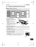
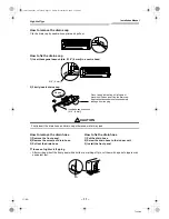
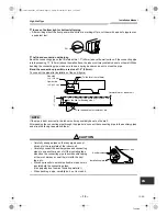
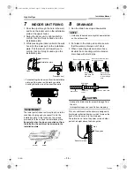
background image

High-Wall Type

Installation Manual

– 23 –

Toshiba

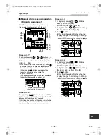
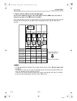
Procedure 

2

Each time you push 

 button, indoor unit 

numbers in the control group change cyclically. 
Select the indoor unit you want to change settings 
for.
The fan of the selected unit runs and the louvers 
start swinging. You can confirm the indoor unit for 
which you want to change settings.

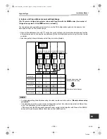
Procedure 

3

Using temp. setup 

 / 

 buttons, specify 

CODE No. [ 

 ].

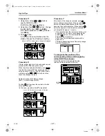
Procedure 

4

Using timer time 

 / 

 buttons, select  SET 

DATA [ 

 ].

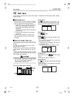
Procedure 

5

Push 

 button. When the display changes from 

flashing to lit, the setup is completed.
• To change settings of another indoor unit, repeat 

from Procedure 

2

.

• To change other settings of the selected indoor 

unit, repeat from Procedure 

3

.

Use 

 button to clear the settings. 

To make settings after 

 button was pushed, 

repeat from Procedure 

2

.

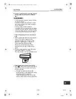
Procedure 

6

When settings have been completed, push 


button to determine the settings. 
When 

 button is pushed, “SETTING” flashes and 

then the display content disappears and the air 
conditioner enters the normal stop mode.
 (While “SETTING” is flashing, no operation of the 
remote controller is accepted.)

„

Change of lighting time of filter 
sign

According to the installation condition, the lighting 
time of the filter sign (Notification of filter cleaning) 
can be changed.
Follow to the basic operation procedure
(

1


2


3


4


5


6

).

• For the CODE No. in Procedure 

3

, specify [01].

• For the [SET DATA] in Procedure 

4

, select the 

SET DATA of filter sign lighting time from the 
following table.

„

To secure better effect of heating

When it is difficult to obtain satisfactory heating due 
to installation place of the indoor unit or structure of 
the room, the detection temperature of heating can 
be raised. Also use a circulator, etc. to circulate 
heat air near the ceiling.
Follow to the basic operation procedure
(

1


2


3


4


5


6

).

• For the CODE No. in Procedure 

3

, specify [06].

• For the SET DATA in Procedure 

4

, select the 

SET DATA of shift value of detection 
temperature to be set up from the table below.

Setup data

Filter sign lighting time

0000

None

0001

150H (Factory default)

0002

2500H

0003

5000H

0004

10000H

Setup data

Detection temp shift value

0000

No shift

0001

+ 1.8 °F (+1 °C)

0002

+ 3.6 °F (+2 °C)

0003

+ 5.4 °F (+3 °C)

(Factory default)

0004

+ 7.2 °F (+4 °C)

0005

+ 9 °F (+5 °C)

0006

+ 10.8 °F (+6 °C)

23-EN

+001111052201_00Ta.book  Page 23  Friday, November 20, 2009  11:45 AM

Содержание Carrier RAV-SP180KRT-UL

Страница 1: ...PLIT TYPE Indoor Unit Model name High Wall Type RAV SP180KRT UL RAV SP240KRT UL Installation Manual Installation Manual 1 English Manuel d installation 43 Français 001111052201_00Ta book Page 1 Friday November 20 2009 11 45 AM ...

Страница 2: ...NT PIPING 14 10 ELECTRIC WORK 17 11 APPLICABLE CONTROLS 22 12 TEST RUN 35 13 TROUBLE SHOOTING 37 Please read this Installation Manual carefully before installing the Air Conditioner This Manual describes the installation method of the outdoor unit For installation of the indoor unit refer to the Installation Manual attached to the indoor unit ADOPTION OF NEW REFRIGERANT This Air Conditioner uses R...

Страница 3: ...allation plate 1 Wireless remote controller 1 Battery 2 Remote control holder 1 Mounting screw Ø0 16 4 mm 1 0 25 mm 6 Pan head wood screw Ø1 8 3 1 mm 0 6 16 mm 2 Screw Ø0 16 4 mm 0 4 10 mm 2 Heat insulator 1 Name Owner s manual Installation manual 2 EN 001111052201_00Ta book Page 2 Friday November 20 2009 11 45 AM ...

Страница 4: ... or fire Be sure to connect ground wire grounding work Incomplete grounding cause an electric shock Do not connect ground wires to gas pipes water pipes lightning rods or ground wires for telephone wires Turn off the circuit breaker and leakage breaker before attempting any electrical work Make sure all circuit breaker and leakage breaker are off Failure to do so may cause electric shock Install t...

Страница 5: ...NE LAYER The characteristics of R410A refrigerant are easy to absorb water oxidizing membrane or oil and its pressure is approx 1 6 times higher than that of refrigerant R22 Accompanied with the new refrigerant refrigerating oil has also been changed Therefore during installation work be sure that water dust former refrigerant or refrigerating oil does not enter the refrigerating cycle To prevent ...

Страница 6: ...rate mist or dew drop or deform or damage resin parts Place where organic solvent is used nearby Place close to a machine generating high frequency Place where the discharged air blows directly into the window of the neighbour house Outdoor unit Place where noise of the outdoor unit is easily transmitted When install the outdoor unit on the boundary with the neighbour pay due attention to the leve...

Страница 7: ...ll Insert the cushion between the indoor unit and wall and tilt the indoor unit for better operation Do not allow the drain hose to get slack Cut the piping hole sloped slightly Make sure to run the drain hose sloped downward The auxiliary piping can be connected to the left rear left rear right right bottom right or bottom left Right Rear right Bottom right Bottom left L Rear left 2 0 50 mm or mo...

Страница 8: ...th the following rules to prevent damage of the indoor units and human injury Do not put a heavy article on the indoor unit Even units are packaged Carry in the indoor unit as it is packaged if possible If carrying in the indoor unit unpacked by necessity be sure to use buffering cloth etc to not damage the unit To move the indoor unit do not apply force to the refrigerant pipe drain pan foamed pa...

Страница 9: ...nt the installation plate on a concrete wall with anchor bolts utilize the anchor bolt holes as illustrated in the above figure 3 Install the installation plate horizontally in the wall CAUTION When installing the installation plate with a mounting screw do not use the anchor bolt hole Otherwise the unit may fall down and result in personal injury and property damage 80 651111012101 80 65111101210...

Страница 10: ...e walls make 0 2 5 mm dia holes in the wall Insert clip anchors for appropriate mounting screws NOTE Secure four corners and lower parts of the installation plate with 6 mounting screws to install it Projection 0 6 15 mm or less Clip anchor local parts Mounting screw 0 16 4 mm 1 0 25 mm Anchor bolt 0 2 5 mm dia hole OK NO GOOD NO GOOD 9 EN 001111052201_00Ta book Page 9 Friday November 20 2009 11 4...

Страница 11: ...ht side of the front panel for the bottom left or right connection with a pair of nippers 3 Changing drain hose For leftward connection bottom leftward connection and rear leftward connection s piping it is necessary to change the drain hose and drain cap Without changing the drain hose position the indoor unit will not fit to the wall How to remove the drain hose The drain hose can be removed by ...

Страница 12: ...with a knife or a marking off pin cut them with a pair of nippers or an equivalent tool How to remove the drain hose 1 Remove the front panel 2 Remove the screws of drain hose 3 Pull out the drain hose How to fix the drain hose 1 Put the drain hose 2 Screw the drain hose to the indoor unit 3 Install the front panel 0 16 4 mm No gap Do not apply lubricating oil refrigerant machine oil when insertin...

Страница 13: ...connecting pipe through the pipe hole connect the connecting pipe to the auxiliary pipes and wrap the facing tape around them CAUTION Carefully arrange pipes so that any pipe does not stick out of the rear plate of the indoor unit Carefully connect the auxiliary pipes and connecting pipes to one another and cut off the insulating tape wound on the connecting pipe to avoid double taping at the join...

Страница 14: ...st be screwed to the installation plate 8 DRAINAGE 1 Run the drain hose sloped downwards NOTE Hole should be made at a slight downward slant on the outdoor side 2 Put water in the drain pan and make sure that the water is drained out of doors 3 When connecting extension drain hose insulate the connecting part of extension drain hose with shield pipe CAUTION Arrange the drain pipe for proper draina...

Страница 15: ...al attached to the outdoor unit Flaring Cut the pipe with a pipe cutter Remove burrs completely Remaining burrs may cause gas leakage Insert a flare nut into the pipe and flare the pipe As the flaring sizes of R410A differ from those of refrigerant R22 the flare tools newly manufactured for R410A are recommended However the conventional tools can be used by adjusting projection margin of the coppe...

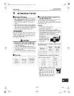
Страница 16: ...insulator with a heat resistance of 248 F 120 C or more must be used for the gas side pipe The pipe connection section of the indoor unit must be heat insulated securely and compactly with the attached heat insulator Air purge Using a vacuum pump perform vacuuming from the charge port of valve of the outdoor unit For details follow to the Installation Manual attached to the outdoor unit Never use ...

Страница 17: ...s when the 2 air conditioners are closely installed Wireless remote controller B setup 1 Press button on the indoor unit to turn the air conditioner ON 2 Point the wireless remote controller at the indoor unit 3 Push and hold button on the wireless remote controller by the tip of the pencil 00 will be shown on the display 4 Press during pushing B will be shown on the display and 00 will be disappe...

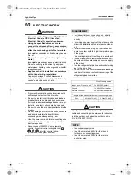
Страница 18: ...ified thickness type and protective devices required Never connect 208 230 V wired remote controller central control wiring blocks etc for control wiring Otherwise the system will fail REQUIREMENT For Indoor Outdoor connecting wire strictly conform to the Local Regulation in each country For wiring of power supply of the outdoor units follow the Installation Manual of each outdoor unit Perform the...

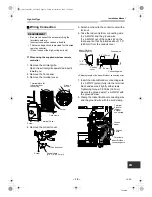
Страница 19: ... so that it protrudes about 11 0 280 mm from the conduit cover 7 Insert the Indoor Outdoor connecting wire 3 x AWG12 polar fully into the terminal block and secure it tightly with screws Tightening torque 0 9 ft lbs 1 2 N m Secure the ground wire 1 x AWG12 with the ground screw 8 Clamp the Indoor Outdoor connecting wire and the ground wire with the cord clamp L1 L2 S L1 L2 S Terminalblock for indo...

Страница 20: ...ront panel 3 Remove the terminal cover and the clamp base 4 Insert the wired remote controller wire fully into the wired remote controller central control terminal block and and secure it tightly with screws Strip off the wire approx 0 4 9 mm to connect Non polarity 2 core wire is used for wiring of the wired remote controller 2 x AWG20 Indoor Outdoor connecting wire Conduit cover 11 0 280 mm 0 08...

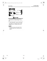
Страница 21: ...r the front panel and the air inlet grille to the indoor unit CAUTION Be sure to refer to the wiring diagram attached inside the front panel Check local electrical cords and also any specific wiring instructions and limitations Do not catch the wired remote controller wire when installing the clamp base Beware of the metal plate edge when working on the unit The edge can be sharp and may cut your ...

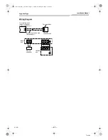
Страница 22: ...or remote controller wiring of indoor unit Remote controller wire Field supply Terminal block Remote controller unit A B L1 L1 L2 L2 S S 208 230 1 60 Outdoor unit High voltage Low voltage Remote controller Indoor unit 21 EN 001111052201_00Ta book Page 21 Friday November 20 2009 11 45 AM ...

Страница 23: ...ing settings Change the settings while the air conditioner is not working Be sure to stop the air conditioner before making settings Procedure 1 Push button and temp setup button simultaneously for at least 4 seconds After a while the display flashes as shown in the figure Confirm that the CODE No is 01 If the CODE No is not 01 push button to erase the display content and repeat the procedure from...

Страница 24: ... of the remote controller is accepted Change of lighting time of filter sign According to the installation condition the lighting time of the filter sign Notification of filter cleaning can be changed Follow to the basic operation procedure 1 2 3 4 5 6 For the CODE No in Procedure 3 specify 01 For the SET DATA in Procedure 4 select the SET DATA of filter sign lighting time from the following table...

Страница 25: ...1 Push and buttons simultaneously for at least 4 seconds to call the service monitor mode The service monitor indicator lights up and the header indoor unit number is displayed first CODE No is also displayed 2 Pushing TEMP buttons select the number of sensor etc CODE No to be monitored See the following table 3 Pushing left side of the button select an indoor unit to be monitored The sensor tempe...

Страница 26: ...he automatic address setup starts and which indicates that address is being set up flashes on the display part During setup of automatic address the remote controller operation is not accepted Required time up to the finish of automatic addressing is approx 5 minutes NOTE In some cases it is necessary to change the address manually after setup of the automatic address according to the system confi...

Страница 27: ...unit of which setup is changed In this time the position of the indoor unit of which setup is changed can be confirmed because fan and louver of the selected indoor unit operate Procedure 3 1 Using temp setup buttons specify CODE No 12 CODE No 12 Line address 2 Using timer time buttons change the line address from 3 to 2 3 Push button In this time the setup finishes when the display changes from f...

Страница 28: ...ed In this case procedure from 2 is repeated Procedure 7 After check of the changed contents push button Setup is determined When pushing button the display disappears and the status becomes the usual stop status When pushing button the operation from the remote controller is not accepted for approx 1 minute If the operation from the remote controller is not accepted even 1 minute or more passed a...

Страница 29: ...t Procedure 3 After confirmation push button to return the mode to the usual mode When pushing button the display disappears and the status becomes the usual stop status When pushing button the operation from the remote controller is not accepted for approx 1 minute Central control system Air conditioners at multiple locations can be controlled individually for each refrigeration system from a con...

Страница 30: ...L2 S Central control device Central control device Central control device Up to 10 units Refrigeration system 1 Refrigeration system 2 Refrigeration system 3 Header indoor unit Follower indoor unit Indoor unit TCC LINK adapter option Required for indoor units other than high wall type Remote controller wiring Remote controller Remote controller Remote controller Group operation up to 8 units OFF a...

Страница 31: ...ain guide and disconnect the ground wire TCJ sensor TC sensor and motor lead louver motor fan motor 3 Remove the screws and detach the electric parts box 4 Remove the electric parts box cover and set bit1 of SW01 on the board to ON Do not touch SW02 as it is used for other setting TC sensor Ground wire 30 EN 001111052201_00Ta book Page 30 Friday November 20 2009 11 45 AM L2 S L1 U3 U4 A B Drain gu...

Страница 32: ...original positions CAUTION Connect the sensor and the motor lead certainly back to the previous position If they are not properly connected the system will not operate or other errors may occur ON MCC 1510 ON 2 1 SW01 B SW01 OFF ON 1 2 ON 1 2 SW02 OFF SW01 ON SW02 OFF Factory default After setting 31 EN 001111052201_00Ta book Page 31 Friday November 20 2009 11 45 AM ...

Страница 33: ...e line addresses If automatic address setup has not been performed successfully set addresses manually Refer to Manual address setup procedure System power ON Automatic address setup Line address manual setting change Are indoor units under group control Are all indoor units under central control set to header units group address 1 Set indoor units under central control to header units again and s...

Страница 34: ...for each refrigeration system Set a line address that is different from any of line addresses of other refrigeration systems If indoor units of the SDI series are operated under central control together with those of the SMMS series set line addresses different from those of the SMMS series 1 1 0 1 1 0 1 1 0 2 1 0 1 1 1 3 1 1 2 1 2 4 1 2 Central control device Refrigeration system 1 Refrigeration ...

Страница 35: ...ing the wired remote controller refer to Manual address setup procedure Line addresses must be unique for each refrigeration system Set a line address that is different from any of line addresses of other refrigeration systems If indoor units of the SDI series are operated under central control together with those of the SMMS series set line addresses different from those of the SMMS series 1 1 0 ...

Страница 36: ...even if the operation stops by thermo OFF In order to prevent a serial operation the forced test run is released after 60 minutes have passed and returns to the usual operation CAUTION Do not use the forced test run for cases other than the test run because it applies an excessive load to the devices In case of wired remote controller Procedure 1 Keep button pushed for 4 seconds or more TEST is di...

Страница 37: ...oor and outdoor units 1 When pushing button for 10 seconds or more Pi sound is heard and the operation changes to a forced cooling operation After approx 3 minutes a cooling operation starts forcedly Check cool air starts blowing If the operation does not start check wiring again 2 To stop a test operation push button once again Approx 1 second The louver closes and the operation stops Check trans...

Страница 38: ...p to 4 troubles The history can be confirmed from both operating status and stop status Procedure 1 When pushing and buttons at the same time for 4 seconds or more the following display appears If Service check is displayed the mode enters in the trouble history mode 01 Order of trouble history is displayed in CODE No window Check code is displayed in CHECK window Indoor unit address in which an e...

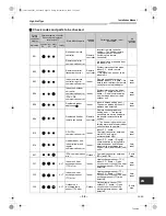
Страница 39: ...etting error The same address as the self address was detected Auto reset E09 Duplicated header remote controllers Remote controller Remote controller address setting error Two remote controllers are set as header in the double remote controller control The header indoor unit stops raising alarm and follower indoor units continue to operate E10 CPU CPU communication error Indoor Indoor P C board C...

Страница 40: ...mpressor breakdown Outdoor Current detect circuit power voltage Minimum frequency was reached in the current releasing control or short circuit current Idc after direct excitation was detected Wiring error of compressor open phase Entire stop H02 Outdoor unit compressor lock Outdoor Compressor circuit Compressor lock was detected Wiring error of compressor open phase Entire stop H03 Outdoor unit c...

Страница 41: ...in the discharge temp releasing control Entire stop P04 ALT Outdoor unit high pressure system error Outdoor High pressure switch The IOL was activated or an error was detected in the high pressure releasing control using the TE Entire stop P05 ALT Open phase detected Outdoor The power cable may be connected incorrectly Check open phase and voltage of the power supply Entire stop P07 ALT Heat sink ...

Страница 42: ...oor IGBT outdoor unit P C board inverter wiring compressor Short circuit protection for compressor drive circuit devices G Tr IGBT was activated Entire stop P29 ALT Outdoor unit position error Outdoor Outdoor unit P C board high pressure switch Compressor motor position error was detected Entire stop P31 ALT Other indoor unit error Indoor Another indoor unit in the group is raising an alarm Entire...

Страница 43: ...High Wall Type Installation Manual 42 Toshiba EN MEMO 42 EN 001111052201_00Ta book Page 42 Friday November 20 2009 11 45 AM ...

Страница 44: ...IE DE RÉFRIGÉRANT 56 10 INSTALLATION ÉLECTRIQUE 59 11 COMMANDES DISPONIBLES 64 12 ESSAI DE FONCTIONNEMENT 77 13 DÉPISTAGE DES PANNES 79 Lisez attentivement de manuel d installation avant d installer le climatiseur Ce manuel traite de la méthode d installation de l unité extérieure Pour l installation de l unité intérieure reportez vous au manuel d installation qui accompagne l unité intérieure ADO...

Страница 45: ...tion 1 Télécommande sans fil 1 Pile 2 Support de télécommande 1 Vis de fixation Ø0 16 4 mm 1 0 25 mm 6 Vis à bois à tête plate Ø1 8 3 1 mm 0 6 16 mm 2 Vis Ø0 16 4 mm 0 4 10 mm 2 Isolant thermique 1 Désignation Manuel du propriétaire Manuel d installation 2 FR 001111052201_00Ta book Page 44 Friday November 20 2009 11 45 AM ...

Страница 46: ... un professionnel qualifié Une installation incorrecte peut entraîner des fuites d eau un incendie une secousse électrique etc Veillez à ce que le climatiseur soit relié à la terre Mise à la terre Une mise à la terre incomplète vous expose à une secousse électrique Ne reliez pas le conducteur de terre à une conduite de gaz ou d eau à un pieu de parafoudre ou à un conducteur de terre de ligne télép...

Страница 47: ...embrane ou huile et sa pression de service est 1 6 fois plus élevée que celle du R22 Pour aller de pair avec le nouveau réfrigérant une autre huile a également été adoptée En conséquence au cours de l installation veillez à ce que de l eau des poussières du réfrigérant ou de l huile de précédente génération ne pénètrent pas dans le circuit de réfrigération Pour éviter de remplir le système avec un...

Страница 48: ...ouillard et des gouttes d eau ou bien déforme et endommage les pièces en résine Un endroit à proximité duquel un solvant organique peut être utilisé Un endroit proche d une machine générant des fréquences élevées Un endroit tel que la sortie d air se fait directement en regard de la fenêtre d une habitation voisine Unité extérieure Un endroit tel que le bruit produit par l unité extérieure soit bi...

Страница 49: ...re gauche et gauche Mur Placez la garniture entre l unité intérieure et le mur puis inclinez l unité intérieure pour un meilleur fonctionnement Veillez à ce que le flexible de vidange soit maintenu Posez le flexible de vidange légèrement incliné Veillez à ce que le flexible de vidange soit légèrement incliné La tuyauterie auxiliaire peut être raccordée à gauche à l arrière gauche à l arrière droit...

Страница 50: ...e ou de blesser quelqu un Ne posez aucun objet sur l unité intérieure Y compris quand elle est encore dans son emballage Transportez l unité intérieure dans son emballage aussi longtemps que possible Quand l unité intérieure doit être extraite de son emballage protégez la au moyen de chiffons pendant toutes les opérations de transport et de manipulation Pour déplacer l unité intérieure n exercez a...

Страница 51: ...r un mur en béton au moyen de boulons d ancrage percez les trous comme le montre l illustration ci dessus 3 Montez la platine d installation horizontalement sur le mur PRÉCAUTION Si la platine d installation est fixée au moyen de vis n utilisez aucun boulon d ancrage Dans le cas contraire l unité intérieure pourrait se désolidariser et blesser quelqu un en tombant 80 651111012101 80 651111012101 0...

Страница 52: ...aires percez des trous de dia 0 2 5 mm Utilisez des chevilles pour les vis de fixation NOTE Assurez la fixation de la platine d installation au quatre coins et en partie basse au moyen de 6 vis de fixation Saillie 0 6 15 mm ou moins Cheville pièces à approvisionner localement Vis de fixation 0 16 4 mm 1 0 25 mm Boulon d ancrage 0 2 5 mm dia du trou OK NON NON 9 FR 001111052201_00Ta book Page 51 Fr...

Страница 53: ...la face avant si le raccordement doit se faire en bas à gauche ou à droite utilisez ces pinces coupantes 3 Modification du flexible de vidange Si le raccordement de la tuyauterie a lieu à gauche en bas à gauche ou à l arrière gauche la position du flexible et du bouchon de vidange doit être modifiée L unité intérieure ne peut pas être fixée au mur sans modifier ces positions Pour déposer le flexib...

Страница 54: ...mplacement de la fente sur la face avant découpez celle ci au moyen de pinces coupantes ou d un outil similaire Pour déposer le flexible de vidange 1 Déposez la face avant 2 Déposez les vis du flexible de vidange 3 Tirez à vous le flexible de vidange Pour poser le flexible de vidange 1 Engagez le flexible de vidange 2 Vissez le flexible de vidange sur l unité intérieure 3 Posez la face avant 0 16 ...

Страница 55: ...onduite de raccordement dans le perçage reliez cette conduite aux conduites auxiliaires et maintenez le tout d un ruban PRÉCAUTION Placez les conduites avec soin pour qu elles ne dépassent pas à l arrière de l unité intérieure Reliez soigneusement les conduites auxiliaires et de raccordement et coupez le ruban isolant de des conduites de raccordement pour qu il n y ait pas double épaisseur à haute...

Страница 56: ... d installation 8 VIDANGE 1 Le flexible de vidange doit cheminer en pente vers le bas NOTE Le perçage doit être légèrement incliné vers l extérieur 2 Versez de l eau dans le carter de vidange et assurez vous que l eau s écoule à l extérieur 3 Si le flexible de vidange doit être prolongé isolez le raccord de rallonge au moyen d un tube de protection PRÉCAUTION Placez le flexible de vidange de façon...

Страница 57: ...e l unité extérieure Évasement de conduite Coupez la conduite à l aide d un coupe tube Ébarbez soigneusement Toute bavure peut provoquer une fuite de gaz Engagez un écrou conique sur la conduite puis évasez celle ci Les dimensions d évasement pour réfrigérant R410A différant de celles du réfrigérant R22 les outils spécialement fabriqués pour le R410A sont vivement conseillés Toutefois vous pouvez ...

Страница 58: ...tion de raccordement de l unité intérieure doit être soigneusement isolée de la chaleur au moyen de l isolant thermique fourni Purge d air À l aide d une pompe à vide reliée à l orifice de charge de la vanne de l unité extérieure réalisez le vide Pour de plus amples détails reportez vous au manuel d installation de l unité extérieure Ne purgez pas avec le réfrigérant de l enceinte scellée de l uni...

Страница 59: ...e 2 télécommandes sans fil pour 2 climatiseurs installés à proximité l un de l autre Réglage de la télécommande sans fil B 1 Appuyez sur la touche de l unité intérieure pour la mettre en marche 2 Dirigez la télécommande sans fil vers l unité intérieure 3 Maintenez la pression sur la touche de la télécommande au moyen d un instrument pointu 00 apparaît sur l afficheur 4 Appuyez sur la touche tandis...

Страница 60: ...a section requis protégez les par les dispositifs prescrits Ne reliez pas les contrôleur de télécommande câblée blocs de commande centralisée au 208 230 V etc Dans ce cas en effet le climatiseur serait défaillant CARACTÉRISTIQUES REQUISES Pour les câbles de liaison conformez vous strictement à la réglementation nationale Pour le câblage de l alimentation de l unité extérieure respectez le manuel d...

Страница 61: ...e de liaison unité intérieure unité extérieure 3 x AWG12 polarisés à fond dans le bornier et assurez vous son maintien à l aide de vis Couple de serrage 0 9 ft lbs 1 2 N m Fixez le câble de terre 1 x AWG12 au moyen de la vis de terre 8 Liez le câble de liaison unité intérieure unité extérieure et le câble de terre au moyen d un serre câble L1 L2 S L1 L2 S Bornier de raccordement des unités intérie...

Страница 62: ...base de serrage 4 Engagez à fond le câble de la télécommande câblée dans le contrôleur de télécommande câblée bloc de commande centralisée et puis serrez soigneusement les vis Dénudez le câble sur environ 0 4 9 mm Pour le câblage du contrôleur de télécommande câblée utilisez un câble non polarisé à 2 conducteurs 2 x AWG20 Câble de liaison unité intérieure unité extérieure Cache de conduit 11 0 280...

Страница 63: ...eure PRÉCAUTION N omettez pas de consulter le schéma de câblage fixé au dos de la face avant Respectez la réglementation électrique locale et toute autre instruction de câblage ou restriction spécifiques Veillez à ne pas écraser le câble du contrôleur de télécommande câblée lors de la pose de la base de serrage Lors de l intervention sur l appareil veillez à ne pas vous blesser sur une arête métal...

Страница 64: ...télécommande d unité intérieure Câble de contrôleur de télécommande Fourniture locale Bornier de raccordement Contrôleur de télécommande A B L1 L1 L2 L2 S S 208 230 1 60 Unité extérieure Haute tension Basse tension Télécom mande Unité intérieure 21 FR 001111052201_00Ta book Page 63 Friday November 20 2009 11 45 AM ...

Страница 65: ...s réglages Modifiez les réglages alors que le climatiseur est arrêté Pour cela arrêtez le climatiseur avant de modifier les réglages Méthode 1 Appuyez en même temps et pendant au moins 4 secondes sur les touches et Quelques instants plus tard l afficheur clignote comme le montre l illustration Confirmez que le CODE No est 01 Si le CODE No n est pas 01 appuyez sur la touche pour effacer l afficheur...

Страница 66: ...heur s éteint tandis que le climatiseur cesse de fonctionner Tandis que SETTING clignote aucun ordre de la télécommande n est accepté Modification du moment où le témoin du filtre s éclaire Il peut être souhaitable compte tenu des conditions d installation de modifier le moment où le témoin de colmatage nettoyage requis du filtre s éclaire Procédez selon la méthode 1 2 3 4 5 6 Pour le CODE No de l...

Страница 67: ...supervision Le témoin du mode de supervision s éclaire et le numéro de l unité intérieure principale s affiche tout d abord CODE No s affiche également 2 En appuyant sur les touches TEMP vous sélectionnez le numéro du capteur etc CODE No à superviser Reportez vous au tableau suivant 3 En appuyant sur côté gauche de la touche vous sélectionnez l unité intérieure à superviser Les capteurs de tempéra...

Страница 68: ...lignote sur l afficheur Pendant l attribution des adresses la télécommande ne peut émettre aucun ordre La durée nécessaire à l attribution automatique des adresses est de l ordre de 5 minutes NOTE Dans certains cas selon la configuration du montage groupé il peut être nécessaire de modifier manuellement l attribution automatique des adresses Données relatives à l unité extérieure CODE No Nom des d...

Страница 69: ...odifiée À ce moment là vous pouvez confirmer l unité intérieure concernée car son ventilateur et son volet d air fonctionnent Méthode 3 1 Au moyen des touches de réglage de température affichez CODE No 12 CODE No 12 adresse de ligne 2 Au moyen des touches de réglage d heure changez l adresse de ligne de 3 à 2 3 Appuyez sur la touche À ce moment là l attribution se termine et les indications de l a...

Страница 70: ...dications de l attribution modifiée Dans le cas présent la méthode reprend à partir de 2 Méthode 7 Après vérification de la modification appuyez sur la touche L attribution est terminée Lorsque vous appuyez sur la touche les indications affichées s éteignent et le climatiseur cesse de fonctionner Après avoir appuyé sur la touche la télécommande ne peut émettre aucun ordre pendant environ 1 minute ...

Страница 71: ...mation appuyez sur la touche pour rétablir le mode habituel de fonctionnement Lorsque vous appuyez sur la touche les indications affichées s éteignent et le climatiseur cesse de fonctionner Après avoir appuyé sur la touche la télécommande ne peut émettre aucun ordre pendant environ 1 minute Système de commande centralisée Les climatiseurs installés dans différentes pièces peuvent être contrôlés in...

Страница 72: ...ande centralisée Dispositif decommande centralisée Dispositif de commande centralisée Maximum 10 unités Système de réfrigération 1 Système de réfrigération 2 Système de réfrigération 3 Unité intérieure principale Unité intérieure esclave Unité intérieure Adaptateur TCC LINK option Requis pour les unités intérieures autres que high wall Télé télécommande Télécommande Télécommande Télécommande Fonct...

Страница 73: ... et le conducteur du moteur moteur de volet d air moteur de ventilateur 3 Déposez les vis et le coffret de raccordement électrique 4 Déposez le couvercle du coffret de raccordement électrique et réglez le bit1 de SW01 de la carte sur ON Ne touchez pas SW02 car il sert à un autre réglage Guide de vidange Capteur TC Vis Conducteur du moteur de ventilateur Conducteur du moteur de volet d air Vis Pour...

Страница 74: ...rigine PRÉCAUTION Reliez les conducteurs de capteurs et de moteurs en position d origine Si vous ne les reliez pas comme à l origine sachez que le système ne fonctionnera pas et que de nombreuses autres erreurs risquent de survenir ON MCC 1510 ON 2 1 SW01 B SW01 OFF ON 1 2 ON 1 2 SW02 OFF SW01 ON SW02 OFF Défaut usine Après réglage 31 FR 001111052201_00Ta book Page 73 Friday November 20 2009 11 45...

Страница 75: ...ous à la section Attribution manuelle des adresses Mise sous tension du système Attribution automatique des adresses Attribution changement manuels des adresses de ligne Les unités intérieures fonctionnent elles en mode groupé Toutes les unités intérieures en commande centralisée sont elles sous le contrôle des unités intérieures principales adresse de groupe 1 Placez à nouveau les unités intérieu...

Страница 76: ... Attribuez une adresse de ligne différente des autres adresses de ligne des systèmes de réfrigération Si les unités intérieures de la série SDI fonctionne sous commande centralisée avec celles de la série SMMS attribuez des adresses de ligne différentes de celles de la série SMMS 1 1 0 1 1 0 1 1 0 2 1 0 1 1 1 3 1 1 2 1 2 4 1 2 Dispositif de commande centralisée Système de réfrigération 1 Système d...

Страница 77: ...ttribution manuelle des adresses Les adresses de ligne doivent être uniques pour chaque système de réfrigération Attribuez une adresse de ligne différente des autres adresses de ligne des systèmes de réfrigération Si les unités intérieures de la série SDI fonctionne sous commande centralisée avec celles de la série SMMS attribuez des adresses de ligne différentes de celles de la série SMMS 1 1 0 3...

Страница 78: ...e fonctionnement s est arrêté du fait de l actionnement du disjoncteur thermique Pour éviter un fonctionnement série la marche forcée est abandonnée 60 minutes plus tard et le fonctionnement normal est rétabli PRÉCAUTION N utilisez pas la marche forcée pour autre chose que la marche forcée car elle applique des contraintes excessives sur les appareils Avec la télécommande câblée Méthode 1 Appuyez ...

Страница 79: ...endant au moins 10 secondes un bip est émis et la marche forcée de refroidissement est commandée Après environ 3 minutes la marche forcée de refroidissement commence Assurez vous que de l air froid est émis Si le fonctionnement ne démarre pas contrôlez le câblage à nouveau 2 Pour arrêter l essai appuyez une nouvelle fois sur la touche environ 1 seconde Le volet d air se ferme et le fonctionnement ...

Страница 80: ...torique peut être confirmé en marche ou p l arrêt Méthode 1 Appuyez simultanément sur les touches et pendant au moins 4 secondes ce qui suit s affiche Si Service check s affiche le mode d historique d erreur est adopté 01 Order of trouble history s affiche dans la fenêtre CODE No Check code s affiche dans la fenêtre CHECK Indoor unit address in which an error occurred s affiche dans N d unité Méth...

Страница 81: ...ieure dupliquée Unité intérieure Erreur d attribution d adresse unité intérieure La même adresse d adresse propre a été détectée Réinitialisation automatique E09 Télécommande d unité principale dupliquée Télécommande Erreur d attribution d adresse de télécommande Deux télécommandes ont la même adresse principale dans une commande centrale double L unité intérieure principale s arrête avec alarme e...

Страница 82: ... extérieure Unité extérieure Carte CI unité extérieure Cas d erreur EEPROM Arrêt total H01 Panne de compresseur d unité extérieure Unité extérieure Circuit de détection de courant tension d alimentation Fréquence minimum atteinte par la commande de courant ou courant de court circuit après détection d excitation directe Arrêt total H02 Verrouillage de compresseur d unité extérieure Unité extérieur...

Страница 83: ...de sortie Arrêt total P04 ALT Erreur de système haute pression d unité extérieure Unité extérieure Contacteur haute pression L IOL a été actionné ou une erreur a été détectée dans la commande de libération haute pression utilisant TE Arrêt total P05 ALT Détection de phase en l air Unité extérieure Câble d alimentation mal connecté Recherche de la phase en l air et mesure de la tension de l aliment...

Страница 84: ... câblage convertisseur compresseur Protection de court circuit pour circuit de commande de compresseur G Tr IGBT actionnée Arrêt total P29 ALT Erreur de position d unité extérieure Unité extérieure Carte CI d unité extérieure contacteur haute pression Détection d erreur de moteur de compresseur Arrêt total P31 ALT Autre erreur d unité intérieure Unité intérieure Une autre unité intérieure du group...

Страница 85: ...High Wall Type Installation Manual 84 Toshiba FR MEMO 42 FR 001111052201_00Ta book Page 84 Friday November 20 2009 11 45 AM ...

Страница 86: ......

Страница 87: ......

Страница 88: ...1111052201 Toshiba 001111052201_00Ta book Page 87 Friday November 20 2009 11 45 AM ...

Отзывы: