24 / 92
Copyright © 2016 TOSHIBA TELI CORPORATION, All rights reserved.
http://www.toshiba-teli.co.jp/en/
D4253386C
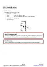
- Line2 (GPIO Input / Output, initial factory setting: Input, I/O connector : 1 pin)
- Input signal specification
Level
: Low 0 ~ 0.5V, High 4.0 ~ 5.0V
Polarity
: High active / Low active (initial factory setting: Low active)
Pulse Width
: Minimum 5
0μs
- Output signal specification
Output Circuit
: 5V CMOS
Maximum Current : +/-32mA
Polarity
: High active / Low active (initial factory setting: Low active)
Signal Source
: TIMER0 ACTIVE
USER OUTPUT
EXPOSURE ACTIVE
FRAME ACTIVE
FRAME TRANSFER
FRAME TRIGGER WAIT
Input / Output circuit diagram
Inside
DC5.0V
10k
Ω
1
3
IOLineModeAll
Notes of external trigger signal:
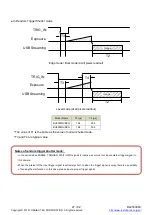
Depending on cable length, cable kinds and input current of trigger input line, Random Trigger Shutter operation may not
satisfy timing specification or camera may not receive EXT_TRIG signal. Please confirm it before use.
Notes of input level:
Line0 and Line2 have different input level. Please use input level within the voltage described in this specification.

