background image

INSTALLATION PROCEDURE FOR OPTIONAL EQUIPMENT


EO15-33002 


7. Expansion I/O Board: B-SA704-IO-QM-R


7- 2 

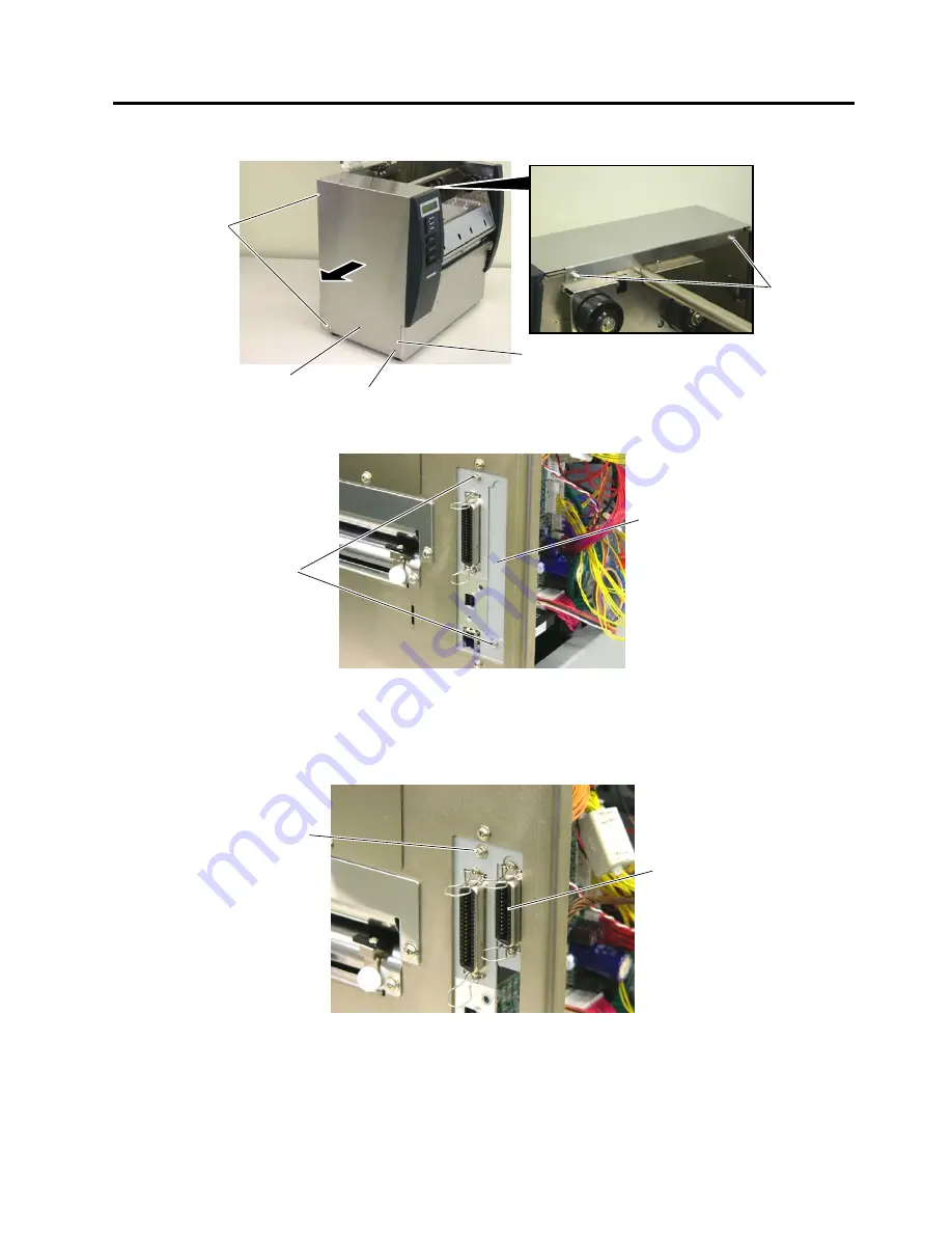
3.  Remove the six screws (B-4x6, FL-4x6 and B-3x8) to detach the left side cover. 


4.  Remove the two SMW-3x6 screws to detach the blind plate. 


NOTE:  Keep the blind plate for future use.


5.  Attach the expansion I/O board to the back of the printer with one of the supplied SMW-3x6 screws. 


FL-4x6 Screw

B-3x8 Screw 

B-4x6 Screw

B-4x6 Screw

Left Side Cover

SMW-3x6

Blind Plate 

SMW-3

6 Screw

Expansion I/O Board 

Содержание B-SX6T Series

Страница 1: ...PRINTED IN JAPAN TOSHIBA Thermal Printer B SX6T SX8T SERIES Document No EO15 33002 Original Mar 2006 Revised Option Installation Manual ...

Страница 2: ...04 RTC QM R 6 1 7 Expansion I O Board B SA704 IO QM R 7 1 CAUTION 1 This manual may not be copied in whole or in part without prior written permission of TOSHIBA TEC 2 The contents of this manual may be changed without notification 3 Please refer to your local Authorised Service representative with regard to any queries you may have in this manual Copyright 2006 by TOSHIBA TEC CORPORATION All Righ...

Страница 3: ...ness 1 pc Cutter Support Plate 1 pc Print Head Cleaner 1 pc Cutter Attaching Screw 2 pcs FL 4x6 Screw 2 pcs SM4x6 Screw 1 pc Installation Manual 1 copy Note for how to use the print head cleaner please refer to the Owner s Manual Installation Procedure 1 Turn the power off 2 Open the right side cover and top covers WARNING 1 Turn the printer power off and disconnect the power cord before installin...

Страница 4: ... 3x8 to detach the left side cover 4 Remove the four FL 4x6 screws to detach the front cover 5 Remove the SM 4x8 screw and operation panel harness to detach the operation panel FL 4x6 Screw B 3x8 Screw B 4x6 Screw FL 4x6 Screw FL 4x6 Screw FL 4x6 Screw SM 4x8 Screw Operation Panel Harness Operation Panel B 4x6 Screw Left Side Cover ...

Страница 5: ...he opening of the cutter unit 8 Install the cutter unit with the supplied four screws cuter attaching screws SM 4x6 and FL 4x6 When installing the cutter unit make sure that the cutter guide does not contact with the platen If so a print failure or noise may occur FL 4x6 Screw FL 4x6 Screw Cutter Support Plate Main Frame Cutter Interface PC Board CN3 Cutter Unit Cutter Harness Cutter Unit FL 4x6 S...

Страница 6: ...cover with the two screws 11 Attach the operation panel and the left side cover on the printer 12 Close the top cover and right side cover 13 After the reassembly is completed perform a test print to confirm that the cutter works properly If the print start position becomes misaligned when media is fed in the reverse direction fine adjust the back feed value using the Back Feed Fine Adjustment pro...

Страница 7: ...itioned 0 1 mm to 0 4 mm above the bottom of the cutter guide plate A 2 Attach the cutter guide plate B with the two FL 4x8 screws so that there is a clearance of 0 5 mm between the cutter guide plate A and cutter guide plate B using a clearance gauge Media loading procedure Owner s Manual Section 2 4 Operation check Owner s Manual Section 2 10 System mode setting System Mode Manual Cleaning Owner...

Страница 8: ...ing List The following parts are supplied with the kit Make sure you have all items shown below Strip Unit 1 pc Strip Harness 1 pc Installation Manual 1 copy Installation Procedure 1 Turn the power off 2 Open the right side cover and top cover 3 Remove the six screws B 4x6 FL 4x6 and B 3x8 to detach the left side cover Top Cover Right Side Cover FL 4x6 Screw B 3x8 Screw B 4x6 Screw B 4x6 Screw ...

Страница 9: ...ront cover 5 Remove the SM 4x8 screw and operation panel harness to detach the operation panel 6 Connect the strip harness to CN5 on the PWM PC Board through the opening of the strip base FL 4x6 Screw FL 4x6 Screw FL 4x6 Screw SM 4x8 Screw Operation Panel Harness Operation Panel Strip Unit Strip Harness Strip Base PWM PC Board Opening CN5 ...

Страница 10: ...pening of the main frame 9 Attach the operation panel and the left side cover on the printer 10 Close the top cover and right side cover After that perform an operation check for a proper strip issue Media loading procedure Owner s Manual Section 2 4 Operation check Owner s Manual Section 2 10 System mode setting System Mode Manual Cleaning Owner s Manual Section 4 1 6 FL 4x6 Screw FL 4x6 Screw FL...

Страница 11: ...r the B SX6T Series Packing List The following parts are supplied with the kit Make sure you have all items shown below Solenoid R 1 pc Connector White Solenoid L 1 pc Connector Yellow RSV PC Board 1 pc Locking Support 3 pcs SM 3x5 Screw 4 pcs Installation Manual 1 copy Installation Procedure 1 Turn the power off 2 Open the right side cover and top cover Top Cover Right Side Cover ...

Страница 12: ... Remove the four SM 4x8 screws to detach the blind plate R and blind plate L 5 Attach the blind plate L to the solenoid L with the two SM 3x5 screws 6 Reverse the blind plate L and attach the three locking supports B 4x6 Screw B 4x6 Screw SM 4x8 Screw SM 4x8 Screw Print Head Front Plate Blind Plate R Blind Plate L SM 3x5 Screw Blind Plate L Solenoid L Locking Support ...

Страница 13: ...rness to CN1 on the RSV PC board 8 Attach the blind plate R to the solenoid R with the two SM 3x5 screws 9 Draw the two harnesses 2 pins 3 pins from the head block then connect the harness 2 pins and the harness 3 pins into CN2 and CN3 on the RSV PC board RSV PC Board CN1 Harness Solenoid L SM 3x5 Screw Solenoid R Blind Plate R Harness 3 pins Harness 2 pins CN3 CN2 RSV PC Board ...

Страница 14: ...e head up link into the spring pin of the solenoid attach the solenoids L and R to the head block Note It is easier to attach the solenoid in the following procedure First remove the plunger from the solenoid Next insert the head up link into the plunger then the plunger into the solenoid Solenoid R Harness Spring Pin Head Up Link Solenoid L Head Up Link Plunger Plunger Solenoid ...

Страница 15: ...ad and the platen Then turn the head lever to the LOCK position 13 Fully push the head up link to the direction indicated by the arrow 1 Push the solenoid toward the head up link as indicated by the arrow 2 then secure the solenoid with the two SM 4x8 screws Solenoid L Solenoid R Head Lever Tag Paper LOCK Position Head Up Link Head Up Link 1 2 SM 4x8 Screw 1 2 SM 4x8 Screw Solenoid L Solenoid R ...

Страница 16: ...bbon Saving Module B SX908 R QM R 3 6 14 After installing the solenoids L and R reassemble the print head front plate so that this part fits into the slot of the shaft 15 Perform a label issue to check the ribbon saving operation Print Head Front Plate Shaft Slot ...

Страница 17: ...HANGE the DIP Switch settings on the Wireless LAN Board Doing so may cause a malfunction 2 MAC address of the Wireless LAN module will be necessary when setting the MAC address filtering function of an access point As it is printed on the top of the wired LAN connector on the Wireless LAN Board write down it on Installation Manual before mounting the covers so that an end user can know the MAC add...

Страница 18: ...ocedure 1 Turn the power off 2 Open the right side cover and top cover 3 Remove the six screws B 4x6 FL 4x6 and B 3x8 to detach the left side cover 4 Remove the two SMW 3x6 screws to detach the blind plate Top Cover Right Side Cover FL 4x6 Screw B 3x8 Screw B 4x6 Screw B 4x6 Screw Left Side Cover SMW 3x6 Blind Plate ...

Страница 19: ...out of the opening of the back of the printer Care must be taken not to hit the antenna against the printer frame as damaged antenna may affect the performance 6 As the following picture shows secure the wireless LAN board to the back of the printer with the two out of the supplied SMW 3x6 screws Opening Wireless LAN Board Antenna SMW 3x6 screw ...

Страница 20: ...A704 WLAN QM R 4 4 7 Secure the wireless LAN board onto the MAIN PC board with the SMW 3x6 screw 8 Connect the wireless LAN power cable to CN12 on the MAIN PC board 9 Connect the LAN cable as shown below SMW 3x6 Screw Wireless LAN Board CN12 MAIN PC Board MAIN PC Board LAN Cable CN17 ...

Страница 21: ...eless LAN Module B SA704 WLAN QM R 4 5 10 Fit the antenna cover to the back of the printer Secure it with the SMW 3x6 screw 11 Reassemble the side panel into the printer Antenna Cover Pass the LAN cable through the cut of the antenna cover LAN Cable SMW 3x6 Screw ...

Страница 22: ...he straight LAN cable with the hub s inverting input function 2 Open the MS DOS prompt then type in telnet 192 168 10 21 default IP address 3 Enter a password to log in Password tecbcp 4 From the top menu change a country code using the following command ctry XX XX new country code See Country Code Table 5 The new country code will become effective by turning the printer off and on again 6 A count...

Страница 23: ...QQ QP R Series Packing List The following parts are supplied with the kit Make sure you have all items shown below SIO PC Board 1 pc Serial Interface Cable Locking Support 1 pc PCB Support Plate 1 pc SMW 3x6 Screw 3 pcs Installation Manual 1 copy NOTE Make sure that the serial interface cable is connected to CN4 on the SIO PC board Installation Procedure 1 Turn the power off 2 Open the right side ...

Страница 24: ...x6 FL 4x6 and B 3x8 to detach the left side cover 4 Remove the two SMW 3x6 screws to detach the blind plate 5 Attach the supplied PCB support plate to the back of the printer with one of the supplied SMW 3x6 screws FL 4x6 Screw B 3x8 Screw B 4x6 Screw B 4x6 Screw Left Side Cover SMW 3x6 Blind Plate SMW 3x6 Screw PCB Support Plate ...

Страница 25: ... CN12 on the MAIN PC board 7 Fit the locking support into the MAIN PC board 8 Secure the SIO PC board to the back of the printer with the two SMW 3x6 screws Fit the locking support into the SIO PC board 9 Reassemble the left side cover SIO PC Board Serial Interface Cable CN12 MAIN PC Board Locking Support MAIN PC Board SMW 3x6 Screw Locking Support SIO PC Board ...

Страница 26: ...ce cable of the real time clock cannot be connected to the MAIN PC board Please remove this optional PC board temporarily prior to installing the real time clock Packing List The following parts are supplied with the kit Make sure you have all items shown below Real Time Clock 1 pc See NOTE SMW 4x8 Screw 1 pc Lithium Battery CR2032 1 pc Installation Manual 1 copy Battery Sticker 1 pc NOTE Make sur...

Страница 27: ...Place the battery with the mark facing up 2 A new battery is supposed to last about 2 years or more but it varies depending on the operating conditions When a new battery is loaded write down the battery replacement date on a supplied battery sticker and attach it to the reverse side of the left side cover as a reminder Battery Socket Lithium Battery Reverse side of Left Side Cover Battery Sticker...

Страница 28: ...cable to CN501 on the MAIN PC board 7 Attach the left side cover which was removed in Step 3 to the back of the printer Care must be taken not to catch the interface cable by the left side cover NOTE When the B SA704 IO QM R expansion I O board or B SA704 RS QM R serial interface board was removed beforehand re install it Real Time Clock SMW 4x8 Screw Interface Cable CN501 MAIN PC Board ...

Страница 29: ...and B 852 QQ QP R Series Packing List The following parts are supplied with the kit Make sure you have all items shown below Expansion I O Board 1 pc See NOTE Blind Plate 1 pc SMW 3x6 Screw 3 pcs Installation Manual 1 copy NOTE Make sure that the interface cable is connected to CN1 on the expansion I O board Installation Procedure 1 Turn the power off 2 Open the right side cover and top cover Inte...

Страница 30: ...to detach the left side cover 4 Remove the two SMW 3x6 screws to detach the blind plate NOTE Keep the blind plate for future use 5 Attach the expansion I O board to the back of the printer with one of the supplied SMW 3x6 screws FL 4x6 Screw B 3x8 Screw B 4x6 Screw B 4x6 Screw Left Side Cover SMW 3x6 Blind Plate SMW 3x6 Screw Expansion I O Board ...

Страница 31: ...ied blind plate to the back of the printer with the supplied two SMW 3x6 screws NOTE The blind plate is not required to be attached when the optional serial interface board is also installed 8 Attach the left side cover which was removed in Step 3 to the back of the printer CN4 MAIN PC Board Interface Cable Expansion I O Board SMW 3x6 Screw Blind Plate Serial Interface Board ...

Отзывы: