23
Connecting your TV
Back connections
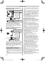
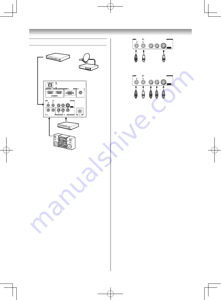
Connection example
RGB/PC
AUDIO
R
1
2
L /MONO
Y
P
R
/C
R
P
B
/C
B
DIGITAL
(2) COMPONENT / VIDEO INPUT
AUDIO
VIDEO
AUDIO
VIDEO
R
L /MONO
PC/HDMI 1
(AUDIO)
AUDIO(FIXED)
(1)
RGB/PC
VIDEO
AUDIO
R
L
/MONO
AUDIO
R
L
/MONO
Y
PR/CR
PB/CB
1
2
3
4
PC/
HDMI 1
(AUDIO)
1
1
AUDIO
(
FIXED
)
COMPONENT VIDEO INPUT
USB
3
1
RGB/PC
PC/HDMI 1
(AUDIO)
COMPONENT
VIDEO INPUT
VIDEO
AUDIO
R
Y
L/MONO
P
R
/C
R
P
B
/C
B
MONITOR
VCR (Normal)
DVD video player
(with component
video outputs)
Set Top Box
or
Audio system
TV back view
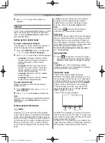
• Before connecting any external equipment,
turn off all main power switches.
• The unauthorized recording of TV
programmes, DVDs, video tapes and other
materials may infringe upon the provisions of
copyright law.
• The
COMPONENT VIDEO INPUT
consists of
three component video signals (
Y
,
P
B
/C
B
,
P
R
/
C
R
) and provides the best picture performance.
These terminals can only be used with the
component video compatible equipment e.g.
DVD video player, etc.
• If you connect to COMPONENT
VIDEO for
the
COMPONENT / VIDEO INPUT
terminals,
screen display will appear changes to
COMPONENT
.
• Additional equipment and cables shown are
not supplied with this TV.
Note:
o
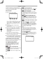
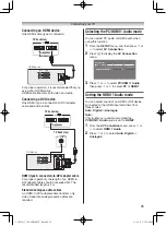
(2) COMPONENT / VIDEO INPUT terminals
Standard video mode:
Use terminals Y, L and R.
RGB/PC
VIDEO
AUDIO
R
L
/MONO
AUDIO
R
L
/MONO
Y
PR/CR
PB/CB
1
2
3
4
PC/
HDMI 1
(AUDIO)
1
1
AUDIO
(
FIXED
)
COMPONENT VIDEO INPUT
USB
3
1
RGB/PC
PC/HDMI 1
(AUDIO)
COMPONENT
VIDEO INPUT
VIDEO
AUDIO
R
Y
L/MONO
P
R
/C
R
P
B
/C
B
MONITOR
Red
White
Yellow
AUDIO
R
L /MONO
Y
P
R
/C
R
P
B
/C
B
(2) COMPONENT / VIDEO INPUT
VIDEO
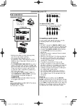
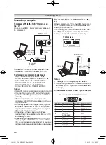
Component video mode:
Use terminals Y, P
B
/C
B
, P
R
/C
R
, L and R.
RGB/PC
VIDEO
AUDIO
R
L
/MONO
AUDIO
R
L
/MONO
Y
PR/CR
PB/CB
1
2
3
4
PC/
HDMI 1
(AUDIO)
1
1
AUDIO
(
FIXED
)
COMPONENT VIDEO INPUT
USB
3
1
RGB/PC
PC/HDMI 1
(AUDIO)
COMPONENT
VIDEO INPUT
VIDEO
AUDIO
R
Y
L/MONO
P
R
/C
R
P
B
/C
B
MONITOR
Red
(Audio)
White
Green
Blue
Red
AUDIO
R
L /MONO
Y
P
R
/C
R
P
B
/C
B
(2) COMPONENT / VIDEO INPUT
VIDEO
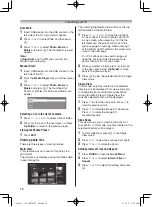
Connecting an audio system
You can enjoy high quality dynamic sound by
connecting the TV to an audio system.
Notes:
• DO NOT connect the
DIGITAL AUDIO
output
terminal to the AC-3 RF input of a Dolby Digital
Receiver with a built-in Dolby Digital decoder.
• Connect the
DIGITAL AUDIO
output terminal
to the
OPTICAL
input of a receiver or
processor.
• Refer to the owner’s manual of the connected
equipment as well.
• When you connect the TV to other equipment,
be sure to turn off the power and unplug all
of the equipment from the wall outlet before
making any connections.
• The output sound of the TV has a wide
dynamic range. Be sure to adjust the audio
amplifier’s volume to a moderate listening level
before turning on the power. Otherwise, the
speakers and your hearing may be damaged
by sudden high volume audio.
• Turn off the amplifier before you connect or
disconnect the TV’s power cord. If you leave
the amplifier power on, the speakers may be
damaged.
Warning:
When you are connecting (via the
DIGITAL
AUDIO
output terminal) an AV decoder that does
not have Dolby Digital decoding function, be sure
to set
PCM
for Digital Output menu (
-
page 19).
Otherwise, the speakers and your hearing may
be damaged by sudden high volume audio.
110419c1_3240PB10ETV_En.indd 23
11.4.19 1:57:15 PM

