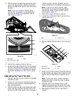
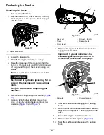
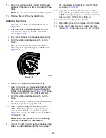
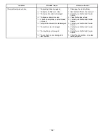
background image

Belt Maintenance

Checking and Adjusting the
Alternator Belt Tension

Service Interval:

Before each use or daily—Check

the condition of the alternator belt.

Every 100 hours—Adjust the alternator belt
tension.

1.

Park the machine on a level surface, engage the
parking brake, and lower the loader arms.

2.

Shut off the engine and remove the key.

3.

Open the hood.

4.

Apply 30 N (22 in-lb) of force to the alternator
belt, midway between the pulleys (

Figure 76

).

g031638

Figure 76

1.

Alternator belt

5.

If the belt does not deflect 11 mm (7/16 inch),
complete the following procedure to tension the
belt:

A.

Loosen the bolt securing the alternator to
the engine and the bolt securing the brace
to the alternator.

B.

Insert a pry bar between the alternator and
engine, and pry out at the alternator.

C.

When you obtain the proper tension, tighten
the alternator and brace bolts to secure the
adjustment.

Controls System
Maintenance

Adjusting the Controls

The factory adjusts the controls before shipping the
machine. However, after many hours of use, you
may need to adjust the traction control alignment,
the N

EUTRAL

position of the traction control, and the

tracking of the traction control in the full forward
position.

Contact your Authorized Service Dealer to adjust the
controls of your machine.

48


Содержание TXL 2000

Страница 1: ...Form No 3434 754 Rev B TXL 2000 Tool Carrier Model No 22530 Serial No 405540000 and Up Model No 22531 Serial No 405540000 and Up Register at www Toro com Original Instructions EN 3434 754 B ...

Страница 2: ...sing this product for purposes other than its intended use could prove dangerous to you and bystanders Do not modify the machine or attachments Read this information carefully to learn how to operate and maintain your product properly and to avoid injury and product damage You are responsible for operating the product properly and safely Visit www Toro com for product safety and operation training...

Страница 3: ... System Maintenance 37 Draining the Water Separator 37 Replacing the Water Separator Filter 37 Replacing the Fuel Filter Canister 38 Checking the Fuel Lines and Connections 38 Bleeding the Fuel System 38 Draining the Fuel Tank s 38 Electrical System Maintenance 39 Electrical System Safety 39 Servicing the Battery 39 Jump Starting the Machine 40 Servicing the Fuses 42 Drive System Maintenance 42 Re...

Страница 4: ...he heavy end and a full load bearing attachment makes the front of the machine the heavy end Most other attachments make the front of the machine the heavy end Have the property or work area marked for buried lines and other objects and do not dig in marked areas Read and understand the content of this Operator s Manual before starting the engine Use your full attention while operating the machine...

Страница 5: ...n cause blindness or severe burns 4 Wear eye protection 9 Flush eyes immediately with water and get medical help fast 5 Read the Operator s Manual 10 Contains lead do not discard g269553 Figure 3 1 120 0625 decal120 0625 120 0625 1 Pinch point hand keep hands away g269556 Figure 4 1 115 4855 4 139 1159 on both loader arms 2 139 1173 5 115 4858 on both loader arms 3 139 1164 on both loader arms 6 1...

Страница 6: ...ssure fluid hazard injection into the body read the Operator s Manual before performing maintenance g275810 Figure 5 1 139 5744 5 139 1171 2 137 5420 6 139 1162 3 136 4863 7 115 4857 4 131 0710 decal115 4857 115 4857 1 Lower the loader arms 4 Curl the bucket 2 Dump the bucket 5 Float the bucket on the ground 3 Raise the loader arms decal136 4863 136 4863 1 Attention read the Operator s Manual Smar...

Страница 7: ...op before servicing keep away from moving parts keep all guards and shields in place 2 Warning receive training before operating the machine 8 Explosion hazard electrocution hazard call the local utilities hotline before beginning work in an area 3 Warning wear hearing protection 9 Crushing hazard keep away from the attachment when operating the machine keep bystanders away from the machine 4 Warn...

Страница 8: ...81 1 Cutting dismemberment hazard fan stay away from moving parts decal93 7814 93 7814 1 Entanglement hazard belt stay away from moving parts keep all guards and shields in place decal106 5976 106 5976 1 Engine coolant under pressure 3 Warning do not touch the hot surface 2 Explosion hazard read the Operator s Manual 4 Warning read the Operator s Manual decal115 4865 115 4865 1 Engine coolant 2 Re...

Страница 9: ...5 2047 1 Warning do not touch the hot surface decal137 7164 137 7164 1 Read the Operator s Manual rotate counter clockwise to disconnect the battery rotate clockwise to connect the battery the negative post is located below the switch the positive post is located to the side of the switch 9 ...

Страница 10: ...ual for fuse information 3 Horn 2 Lighter 4 Electric g269560 Figure 8 1 133 8062 decal133 8062 133 8062 g269558 Figure 9 1 137 5409 on both loader arms decal137 5409 137 5409 g269559 Figure 10 1 125 6694 decal125 6694 125 6694 1 Tie down location 10 ...

Страница 11: ...0 Joystick controls 5 Power socket 11 Loader arm attachment tilt lever 6 Throttle switch 12 Loader valve lock Key Switch The key switch used to start and shut off the engine has 3 positions OFF RUN and START Refer to Starting the Engine page 22 Parking Brake Switch Press the parking brake switch to engage and disengage the parking brake Figure 12 The parking brake also engages automatically when y...

Страница 12: ...raction control forward Figure 14 g264830 Figure 14 To move rearward move the traction control rearward Figure 15 Important When reversing look behind you for obstructions and keep your hands on the reference bar g264831 Figure 15 To turn right rotate the traction control clockwise Figure 16 g264833 Figure 16 To turn left rotate the traction control counterclockwise Figure 17 g264832 Figure 17 To ...

Страница 13: ...ce Secure the loader valve with the lock in addition to the cylinder locks any time you need to shut off the machine with the loader arms raised Refer to Using the Cylinder Locks page 29 To set the lock lift up on it so that it clears the hole in the control panel and swing it to the left in front of the loader arm lever pushing it down into the locked position Figure 19 g300649 Figure 19 1 Loader...

Страница 14: ...he operating status various diagnostics and other information about the machine Figure 22 There is a splash screen and main information screen of the InfoCenter You can switch between the splash screen and main information screen at any time by pressing any of the InfoCenter buttons and then selecting the appropriate directional arrow g264015 Figure 22 1 Indicator light 3 Middle button 2 Right but...

Страница 15: ...er for more information on the Faults menu and the information contained there Service The Service menu contains information on the machine such as hours of use and other similar numbers Diagnostics The Diagnostics menu displays the state of each machine switch sensor and control output You can use this to troubleshoot certain issues as it will quickly tell you which machine controls are on and wh...

Страница 16: ...lling the machine speed and optimizing performance Protected Menus Grants access to protected menus Protect Settings Changes whether a pin is required in Protected Menus Transport Speed Controls the maximum speed while in transport About Menu Item Description Model Lists the model number of the machine Serial Lists the serial number of the machine Software Lists the system software revision of the...

Страница 17: ... to enter the PIN code Figure 26D Note If the InfoCenter accepts the PIN code and the protected menu is unlocked the word PIN displays in the upper right corner of the screen You can view and change the settings in the PROTECTED MENU Once you access the PROTECTED MENU scroll down to PROTECT SETTINGS option Use the right button to change the setting Setting the Protect Settings to OFF allows you to...

Страница 18: ...inches Length 251 cm 99 inches Height 173 cm 68 inches Weight 2828 kg 6 235 lb Operating capacity 35 of tipping capacity1 907 kg 2 000 lb Tipping capacity1 2592 kg 5 715 lb Wheelbase 137 cm 54 inches Dump height with standard bucket 163 cm 64 inches Reach fully raised with standard bucket 66 cm 26 inches Height to hinge pin with standard bucket in highest position 251 cm 99 inches 1 The operating ...

Страница 19: ...proved fuel container Do not remove the fuel cap or fill the fuel tank while the engine is running or hot Do not add or drain fuel in an enclosed space Do not store the machine or fuel container where there is an open flame spark or pilot light such as on a water heater or other appliance If you spill fuel do not attempt to start the engine avoid creating any source of ignition until the fuel vapo...

Страница 20: ... distributor for more information on biodiesel Filling the Fuel Tanks Fuel tank capacity 35 L 9 3 US gallons per tank 1 Park the machine on a level surface engage the parking brake and lower the loader arms 2 Shut off the engine and remove the key 3 Remove the fuel cap 4 Fill the tank with fuel up to the filler neck 5 Install the cap g303269 Figure 27 1 Fuel tank caps Performing Daily Maintenance ...

Страница 21: ...oles and hidden hazards Ensure that all the drives are in neutral before starting the engine Start the engine only from the operator s position on the platform Use care when approaching blind corners shrubs trees or other objects that may obscure vision Slow down and use caution when making turns and crossing roads and sidewalks Watch for traffic Stop the attachment when you are not working Stop t...

Страница 22: ... do the following Shut off the machine and remove the key Remove all individuals from the work area Immediately contact the proper emergency and utility authorities to secure the area If you damage a fiber optic cable do not look into the exposed light Do not leave the operator s platform if the machine is charged with electricity You will be safe as long as you do not leave the platform Touching ...

Страница 23: ...h when leaving the traction unit even if just for a few seconds Using Attachments This is a multipurpose machine intended for use in various activities It is designed to operate safely with a variety of Toro manufactured attachments each of which performs a specialized function Toro accepts no liability for machine damage or personal injury that results from the use of other manufacturers attachme...

Страница 24: ...female connector onto the male connector on the machine 5 Push the attachment male connector into the female connector on the machine 6 Confirm that the connection is secure by pulling on the hoses Removing an Attachment 1 Park the machine on a level surface 2 Lower the attachment to the ground 3 Shut off the engine and remove the key 4 Raise the quick attach pins by rotating the levers outward 5 ...

Страница 25: ...ent fires Clean up oil or fuel spills Keep all parts in good working condition and all hardware tightened Do not touch parts that may be hot from operation Allow them to cool before attempting to maintain adjust or service the machine Use care when loading or unloading the machine into a trailer or truck Moving a Non Functioning Machine In an emergency the machine can be moved forward by actuating...

Страница 26: ...d by law Please carefully read all the safety instructions Knowing this information could help you or bystanders avoid injury Refer to your local ordinances for trailer and tie down requirements WARNING Driving on the street or roadway without turn signals lights reflective markings or a slow moving vehicle emblem is dangerous and can lead to accidents causing personal injury Do not drive the mach...

Страница 27: ...e with full attachment or non load bearing attachment drive the machine forward up the ramp s 2 Machine with empty or no attachment back the machine up the ramp s 6 Lower the loader arms all the way down 7 Engage the parking brake if equipped shut off the engine and remove the key 8 Use the metal tie down loops on the machine to securely fasten the machine to the trailer or truck with straps chain...

Страница 28: ...per with the safety devices Attachments can change the stability and the operating characteristics of the machine Use only genuine Toro replacement parts If any maintenance or repair requires the loader arms to be in the raised position secure the arms in the raised position with the hydraulic cylinder lock s Recommended Maintenance Schedule s Maintenance Service Interval Maintenance Procedure Aft...

Страница 29: ...lt Authorized Service Dealer only Replace the alternator fan belt refer to the engine owner s manual for instructions Every 800 hours Change the engine coolant Every 1 000 hours Replace the drive motor planetary gear oil Replace the hydraulic oil and filters if using Toro fluid Every 1 500 hours Replace all moving hydraulic hoses Yearly Replace the air cleaner filter Yearly or before storage Check...

Страница 30: ...n the posts on the sides of the machine and secure with the pins 6 Lower the loader arms Accessing Internal Components WARNING Opening or removing covers hoods and screens while the engine is running could allow you to contact moving parts seriously injuring you Before opening any of the covers hoods and screens shut off the engine remove the key from the key switch and allow the engine to cool Op...

Страница 31: ...p rod to access the internal components Figure 39 g267537 Figure 40 1 Prop rod Removing the Rear Screen 1 Open the rear access cover refer to Opening the Rear Access Cover page 31 2 Loosen the 2 bolts securing the bottom of the screen Figure 41 3 Loosen the 2 knobs on the screen Figure 41 g260063 Figure 41 1 Knob 2 2 Bolt 2 4 Lift the screen and remove it Figure 41 Removing the Bottom Plate 1 Remo...

Страница 32: ...e cover assembly to the machine Figure 44 g303492 Figure 44 1 Bolt 4 2 Front cover assembly 3 Remove the cover assembly Figure 44 Lubrication Lubricating the Machine Service Interval Before each use or daily Grease immediately after every washing Grease Type General purpose grease 1 Park the machine on a level surface engage the parking brake and lower the loader arms 2 Shut off the engine and rem...

Страница 33: ...y Check the air filter service indicator Every 100 hours Remove the air cleaner cover and clean out debris Clean more often in dirty or dusty conditions Yearly Replace the air cleaner filter Check the air cleaner body for damage which could cause an air leak Replace the body if it is damaged Check the intake system for leaks damage or loose hose clamps Service the air cleaner filter only when the ...

Страница 34: ...igure 49 if it shows red Servicing the Engine Oil Service Interval Before each use or daily Check the engine oil level After the first 50 hours Change the engine oil and filter Every 400 hours Change the engine oil and filter Service more frequently if conditions are extremely dusty or sandy Engine Oil Specifications Oil Type Detergent diesel engine oil API service CH 4 or higher Crankcase Capacit...

Страница 35: ...h and you run the engine you may damage the engine g264959 Figure 54 6 Close the hood Changing the Engine Oil and Filter 1 Start the engine and let it run for 5 minutes Note This warms the oil so that it drains better 2 Park the machine on a level surface 3 Raise the loader arms and secure with the cylinder locks refer to Installing the Cylinder Locks page 29 4 Engage the parking brake shut off th...

Страница 36: ...32 9 Place a shallow pan or rag under the filter to catch oil 10 Change the oil filter Figure 56 g031261 Figure 56 11 Remove the oil fill cap and slowly pour approximately 80 of the specified amount of oil in through the valve cover 12 Check the oil level 13 Slowly add additional oil to bring the level to the upper hole on the dipstick 14 Replace the fill cap 15 Install the front cover assembly 16...

Страница 37: ... Figure 57 10 Install the rear screen and tighten the knobs and bolts to secure it 11 Close the rear access cover and install the fastener to secure it 12 Bleed the fuel system refer to Bleeding the Fuel System page 38 Replacing the Water Separator Filter Service Interval Every 500 hours 1 Park the machine on a level surface engage the parking brake and lower the loader arms 2 Shut off the engine ...

Страница 38: ...n and tighten the knobs and bolts to secure it 11 Close the rear access cover and install the fastener to secure it Checking the Fuel Lines and Connections Service Interval Every 400 hours Yearly whichever comes first Inspect the fuel lines and connections for deterioration damage or loose connections Tighten any loose connections and contact your Authorized Service Dealer for assistance in fixing...

Страница 39: ... arms 2 Shut off the engine and remove the key 3 Open the rear access cover 4 Turn the battery disconnect switch to the ON or OFF position to perform the following To energize the machine electrically rotate the battery disconnect switch clockwise to the ON position Figure 60 To de energize the machine electrically rotate the battery disconnect switch counterclockwise to the OFF position Figure 60...

Страница 40: ... a solution of baking soda and water 5 Rinse the battery with clear water 6 Coat the battery posts and cable connectors with Grafo 112X skin over grease Toro Part No 505 47 or petroleum jelly to prevent corrosion 7 Install the battery refer to Installing the Battery page 40 Installing the Battery 1 Place the battery on the battery tray and secure it with the wing nut and rod Figure 61 2 Install th...

Страница 41: ...are tight and level Place a damp cloth if available over any vent caps on both batteries Also ensure that the machines do not touch and that both electrical systems are off and at the same rated system voltage These instructions are for negative ground systems only 5 Connect the positive cable to the positive terminal of the discharged battery that is wired to the starter or solenoid as shown in F...

Страница 42: ...ould be blown Drive System Maintenance Replacing the Drive Motor Planetary Gear Oil Service Interval Every 1 000 hours Oil Type SAE 85W 140 gear oil Capacity 0 9 L 30 fl oz 1 Start the engine and drive the machine for 5 minutes Note This warms the gear oil so that it drains better 2 Park the machine on a level surface so that the drain plug is in the 6 o clock position Figure 65 engage the parking...

Страница 43: ...rface and engage the parking brake 2 With the bucket installed and angled downward lower it into the ground so that the front of the traction unit lifts off the ground a few centimeters inches 3 Shut off the engine and remove the key 4 Using a water hose or pressure washer remove dirt from each track system Important Ensure that you use high pressure water to wash only the track area Do not use a ...

Страница 44: ...d lower it into the ground so that the front of the traction unit lifts off the ground a few centimeters inches and the machine tips back onto the block until the track is completely off the ground Note If you do not have a bucket raise the machine and support it using jackstands rated for the weight of the machine refer to Specifications page 18 4 Shut off the engine and remove the key 5 Loosen t...

Страница 45: ...e machine 6 Remove the locking bolt spacer and nut Figure 70 7 Using a 1 2 inch drive ratchet release the drive tension by turning the tensioning screw clockwise Figure 70 and Figure 72 g262083 Figure 72 1 Sprocket 4 Ratchet 1 2 inch 2 Track 5 Road wheel 4 3 Front wheel 8 Remove the segment of the drive sprocket not engaged with the track Important If you do not remove the sprocket segment it may ...

Страница 46: ...ts to 247 to 301 N m 182 to 222 ft lb 8 Start the engine and disengage the parking brake 9 Move the traction control forward until both drive sprocket segments engage the track 10 Apply thread locking compound to the bolts of the other drive sprocket segment that you removed and install the sprocket segment Figure 74 Torque the bolts to 247 to 301 N m 182 to 222 ft lb Note Install the sprocket so ...

Страница 47: ...dirt or other debris from the radiator screen with compressed air Checking the Engine Coolant Level The cooling system is filled with a 50 50 solution of water and permanent ethylene glycol antifreeze 1 Park the machine on a level surface lower the loader arms engage the parking brake and shut off the engine 2 Remove the key from the key switch and allow the engine to cool 3 Open the hood 4 Check ...

Страница 48: ...ete the following procedure to tension the belt A Loosen the bolt securing the alternator to the engine and the bolt securing the brace to the alternator B Insert a pry bar between the alternator and engine and pry out at the alternator C When you obtain the proper tension tighten the alternator and brace bolts to secure the adjustment Controls System Maintenance Adjusting the Controls The factory...

Страница 49: ...o Premium Transmission Hydraulic Tractor Fluid refer to your Authorized Service Dealer for more information Toro PX Extended Life Hydraulic Fluid refer to your Authorized Service Dealer for more information If either of the above Toro fluids are not available you may use another Universal Tractor Hydraulic Fluid UTHF but they must be only conventional petroleum based products The specifications mu...

Страница 50: ... remove the key 5 Remove the front cover refer to Removing the Front Cover page 32 6 Clean the area around the filler neck of the hydraulic tank Figure 78 g263507 Figure 78 1 Filler neck cap 7 Remove the filler neck cap and check the fluid level on the dipstick Figure 79 Note The fluid level should be between the 2 notches of the dipstick while the arms are lowered or at the lower notch while the ...

Страница 51: ...ear Access Cover page 31 8 Remove the rear screen refer to Removing the Rear Screen page 31 9 Place a drain pan under the rear filter and replace the filter Figure 81 g263575 Figure 81 10 Clean up any spilled fluid 11 Start the engine and let it run for about 2 minutes to purge air from the system 12 Shut off the engine and check for leaks 13 Check the fluid level in the hydraulic tank refer to Ch...

Страница 52: ...rain plug on the front of the machine Figure 83 g303493 Figure 83 1 Drain plug 7 Remove the drain plug and allow the oil to drain into the pan Figure 83 8 When the oil is finished draining install and tighten the drain plug Note Dispose of the used oil at a certified recycling center 9 Fill the hydraulic tank with hydraulic fluid refer to Hydraulic Fluid Specifications page 49 10 Start the engine ...

Страница 53: ...tant Do not overtighten the setscrews otherwise you may damage the adjustment screw threads Cleaning Removing Debris Service Interval Before each use or daily Important Operating the engine with blocked screens and or cooling shrouds removed will result in engine damage from overheating 1 Park the machine on a level surface and lower the loader arms 2 Shut off the engine remove the key and allow t...

Страница 54: ... the key wait for all moving parts to stop and allow the machine to cool before storing it Do not store the machine or fuel near flames Storage 1 Park the machine on a level surface engage the parking brake and lower the loader arms 2 Shut off the engine and remove the key 3 Remove dirt and grime from the entire machine Important You can wash the machine with mild detergent and water Do not pressu...

Страница 55: ...resh fuel 2 There is air in the fuel 2 Bleed the fuel system and check for air leaks at fuel hose connections and fittings between the fuel tank and engine 3 The engine is overheating 3 Refer to The engine overheats The engine starts but does not keep running 4 The air cleaner filters are dirty 4 Service the air filters 1 The crankcase oil level is incorrect 1 Fill or drain to the Full mark 2 The ...

Страница 56: ...are open 4 Close the bypass valves 5 A traction pump drive coupler is loose or broken 5 Contact your Authorized Service Dealer 6 Pump and or wheel motor is damaged 6 Contact your Authorized Service Dealer 7 The control valve is damaged 7 Contact your Authorized Service Dealer 8 The relief valve is damaged 8 Contact your Authorized Service Dealer The machine does not drive 9 The cooling fans are da...

Страница 57: ...Notes ...

Страница 58: ...Notes ...

Страница 59: ...Notes ...

Страница 60: ...to restaurants grocery stores hotels schools and hospitals and on a wide variety of products Additionally some online and mail order retailers provide Prop 65 warnings on their websites or in catalogs How do the California warnings compare to federal limits Prop 65 standards are often more stringent than federal and international standards There are various substances that require a Prop 65 warnin...

Отзывы: