background image

4

Installing Rear Weights

Parts needed for this procedure:

Varies

Rear weights (size varies with configuration)

Procedure

This machine complies with EN ISO 5395 and ANSI B71.4-2017 when equipped with rear weights and/or
41 kg (90 lb) of calcium chloride ballast is added to rear wheels. Use the following charts to determine the
combinations of weights required for your configuration. Order parts from your local authorized Toro distributor.

Weight P/N 110-8985-03

Groomers, roller

brushes, and/or

baskets

Number of weights

to meet ANSI (US)

standards

Number of weights to

meet CE (European)

standards

Fasteners (2 each

required) for weights

Weight Location

No

0

0

N/A

N/A

Yes

4

4

3231-7 Carriage Bolt,

104-8301 Nut

1 on top of bumper and

3 under bumper

Important:

Always install tubes inside the rear tires before calcium chloride is installed. If a puncture

occurs in a tire with calcium chloride, remove the machine from the turf area as quickly as possible. To
prevent possible damage to the turf, immediately soak the affected area with water.

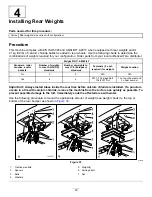
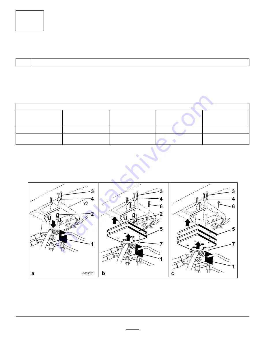
Use the following procedure to mount the appropriate amount of weight (see weight charts) to the top or
bottom of the rear bumper as shown in

Figure 33

.

g005526

Figure 33

1.

Traction manifold

5.

Weight(s)

2.

Spacers

6.

Carriage bolt

3.

Bolts

7.

Nut

4.

Washers

20


Содержание Reelmaster 5610

Страница 1: ...Form No 3450 187 Rev A Reelmaster 5610 Traction Unit Model No 03678 Serial No 410500000 and Up Model No 03678TE Serial No 409900000 and Up Register at www Toro com Original Instructions EN 3450 187 ...

Страница 2: ...prove dangerous to you and bystanders Read this information carefully to learn how to operate and maintain your product properly and to avoid injury and product damage You are responsible for operating the product properly and safely Visit www Toro com for more information including safety tips training materials accessory information help finding a dealer or to register your product Whenever you ...

Страница 3: ...he Air Cleaner 44 Checking the Engine Oil Level 44 Servicing the Engine Oil and Filter 45 Fuel System Maintenance 46 Draining the Fuel Water Separator 47 Bleeding the Fuel System 47 Checking the Fuel Lines and Connections 47 Changing the Fuel Water Separator Filter 48 Draining and Cleaning the Fuel Tank 48 Cleaning the Fuel Intake Screen 48 Electrical System Maintenance 49 Electrical System Safety...

Страница 4: ...hine Do not operate the machine without all guards and other safety protective devices in place and functioning properly on the machine Keep bystanders and children out of the operating area Never allow children to operate the machine Shut off the engine remove the key and wait for all movement to stop before you leave the operator s position Allow the machine to cool before adjusting servicing cl...

Страница 5: ...d the Operator s Manual 10 Contains lead do not discard decal93 6689 93 6689 1 Warning do not carry passengers decal93 6696 93 6696 1 Stored energy hazard read the Operator s Manual decal93 7272 93 7272 1 Cutting dismemberment hazard fan stay away from moving parts decal106 6754 106 6754 1 Warning do not touch the hot surface 2 Cutting dismemberment hazard fan entanglement hazard belt stay away fr...

Страница 6: ...ter pin to the hole closest to the rod bracket and then remove the lift arm and pivot yoke decal120 4158 120 4158 1 Read the Operator s Manual 3 Engine preheat 2 Engine start 4 Engine stop decal121 5644 121 5644 1 Light switch 6 Slow 2 Engage 7 Lower 3 Power take off 8 Raise 4 Disengage 9 Read the Operator s Manual 5 Fast decal133 8062 133 8062 6 ...

Страница 7: ...u are trained 4 Tipping hazard drive slowly when turning do not turn sharply while traveling fast only drive on slopes with the cutting units lowered always wear a seatbelt 2 Warning wear hearing protection 5 Warning do not park on slopes engage the parking brake lower the cutting units shut off the engine and remove the ignition key before leaving the machine 3 Thrown object hazard keep bystander...

Страница 8: ...he machine If possible keep the cutting units lowered to the ground while operating the machine on slopes Raising the cutting units while operating on slopes can cause the machine to become unstable 1 Warning read the Operator s Manual do not operate this machine unless you are trained 4 Tipping hazard do not drive across or down slopes greater than 15 only drive on slopes with the cutting units l...

Страница 9: ... 11 Engine coolant 16 Fluids 2 Brake functions 7 Engine oil 12 Engine oil level 17 Capacity 3 Check every 8 hours 8 Fan belt 13 Fuel 18 Fluid interval hours 4 Hydraulic fluid 9 Battery 14 Read the Operator s Manual 19 Filter interval hours 5 Tire pressure 10 Radiator screen 15 Fuel Water separator 9 ...

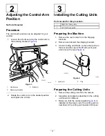
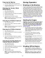
Страница 10: ...the normal operating position 1 Preparing the Machine No Parts Required Procedure 1 Park the machine on a level surface lower the cutting units and engage the parking brake 2 Shut off the engine remove the key and wait for all moving parts to stop 3 Check the tire air pressure before use refer to Checking the Tire Air Pressure page 52 Note The tires are overinflated for shipping Adjust the tire ai...

Страница 11: ...ont hose guide 1 Left front hose guide Preparing the Machine 1 Remove the reel motors from the shipping brackets 2 Remove and discard the shipping brackets 3 At each cutting unit lift arm remove the lynch pin that secures the cap to the lift arm pivot yoke and remove the cap Figure 4 g003975 Figure 4 1 Lynch pin 2 Cap Preparing the Cutting Units 1 Remove the cutting units from the cartons 2 Assemb...

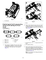
Страница 12: ...to the bracket Figure 7 g375689 Figure 7 1 Hairpin 2 Remove the 2 flange locknuts 3 8 inch and 2 carriage bolts 3 8 x 1 1 4 inches that secure the turf compensator bracket to the cutting unit frame Figure 8 g375690 Figure 8 1 Carriage bolt 3 8 x 1 1 4 inches 3 Flange locknut 3 8 inch 2 Turf compensator bracket 3 Remove the flange locknut 3 8 inch that secures the capscrew of the turf compensation ...

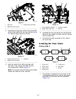
Страница 13: ...ose guide aligns toward the centerline of the machine g375687 Figure 11 1 Turf compensator bracket 3 Stud hose guide 2 Flange locknut 3 8 inch 4 Inboard 6 Assemble the hose guide and turf compensator bracket to the cutting unit frame with the 2 flange locknuts 3 8 inch 7 Torque the locknuts and bolts to 37 to 45 N m 27 to 33 ft lb Installing the Hose Guide Cutting Units 5 g375672 Figure 12 1 Cutti...

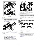
Страница 14: ...hose guide aligns toward the centerline of the machine g375688 Figure 15 1 Stud hose guide 3 Flange locknut 3 8 inch 2 Turf compensator bracket 4 Inboard 4 Assemble the hose guide and turf compensator bracket to the cutting unit frame with the 2 flange locknuts 3 8 inch 5 Torque the locknuts to 37 to 45 N m 27 to 33 ft lb Positioning the Turf Compensating Spring Cutting Unit 2 g379514 Figure 16 1 ...

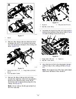
Страница 15: ...frame and remove the compensation spring from the cutting unit Figure 19 Note Do not remove the flange serrated nut from the capscrew g375691 Figure 19 1 Capscrew 3 Flange locknut 3 8 inch 2 Right tab Carrier frame 4 Assemble the capscrew of the turf compensation spring to the right tab of the carrier frame Figure 20 with the flange locknut 3 8 inch g375694 Figure 20 1 Flange locknut 3 8 inch 3 Ca...

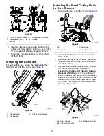
Страница 16: ...a cutting unit under the lift arm Figure 23 g375274 Figure 23 1 Cap 3 Lift arm yoke 2 Snapper pin 4 Carrier frame shaft 2 Assemble the lift arm yoke onto the carrier frame shaft 3 Assemble the cap to the pivot arm shaft and align the holes in the carrier frame shaft pivot arm shaft and cap 4 Secure the cap and the carrier frame shaft to the lift arm yoke with the snapper pin Locking the Cutting Un...

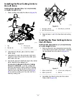
Страница 17: ...to prevent the cutting units from rotating downhill when cutting across the face of a hill Use the hole in the lift arm pivot shaft Figure 25 to lock the cutting unit Use the slot for a steering cutting unit g375251 Figure 26 1 Snap pin positions 3 Slot lift arm pivot shaft 2 Hole lift arm pivot shaft 5 Repeat steps 1 and 2 for the other rear cutting unit Installing the Rear Cutting Units to the L...

Страница 18: ...shaft 2 Hole lift arm pivot shaft 5 Slide a cutting unit under the lift arm Figure 30 g375239 Figure 30 1 Lynch pin 3 Lift arm 2 Lift arm shaft 4 Washer 6 Insert the lift arm shaft into the lift arm and secure shaft to the arm with the lynch pin and washer 7 Repeat steps 1 through 6 for the other rear cutting unit Installing the Cutting Unit Lift Arm Chains Secure the lift arm chain to the chain b...

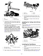
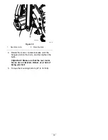
Страница 19: ...olts 4 Rotate the motor counterclockwise until the flanges encircle the bolts and then tighten the bolts Important Make sure that the reel motor hoses are not twisted kinked or at risk of being pinched 5 Torque the mounting bolts to 27 to 33 ft lb 19 ...

Страница 20: ...ds Number of weights to meet CE European standards Fasteners 2 each required for weights Weight Location No 0 0 N A N A Yes 4 4 3231 7 Carriage Bolt 104 8301 Nut 1 on top of bumper and 3 under bumper Important Always install tubes inside the rear tires before calcium chloride is installed If a puncture occurs in a tire with calcium chloride remove the machine from the turf area as quickly as possi...

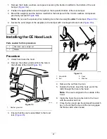
Страница 21: ...nstalling the CE Hood Lock Parts needed for this procedure 1 Hood lock seal and jam nut 1 Washer Procedure 1 Unlatch and raise the hood 2 Remove the rubber grommet from the hole in the left side of the hood Figure 34 g004143 Figure 34 1 Rubber grommet 3 Ensure that the seal is assembled to the hood lock Figure 35 g375326 Figure 35 1 Hood latch 3 Seal 2 Nut 4 Washer 4 Remove the nut from the lock 5...

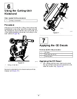
Страница 22: ...f the bedbar adjusting screws are not resting on the work surface Figure 36 g003985 Figure 36 1 Cutting unit kickstand Secure the kickstand to the chain bracket with the snapper pin Figure 37 g004144 Figure 37 7 Applying the CE Decals Parts needed for this procedure 1 CE decal 1 Production year decal 1 Warning decal Applying the CE Decal 1 Use rubbing alcohol and a clean rag to clean the area of t...

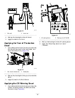
Страница 23: ...igure 39 g375339 Figure 39 1 Year of production decal 2 Serial plate 2 Remove the backing from the year of production decal 3 Apply the decal to the floor bracket Applying the CE Warning Decal 1 Use rubbing alcohol and a clean rag to clean the surface of warning decal 133 2930 and allow the decal to dry Figure 40 g375338 Figure 40 1 CE warning decal 2 Warning decal 133 2930 2 Remove the backing fr...

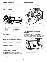
Страница 24: ...ow far you press the pedal For no load maximum ground speed fully press the pedal while the throttle is in the FAST position To stop reduce foot pressure on the traction pedal and allow it to return to the center position Mow Speed Limiter When the mow speed limiter Figure 43 is flipped up it controls the mow speed and allows the cutting units to be engaged Each spacer adjusts the mowing speed by ...

Страница 25: ...nd stops the cutterheads when the cutterheads are enabled in the mow mode Headlight Switch Pivot the switch downward to turn on the headlights Figure 44 Enable Disable Switch Use the enable disable switch Figure 44 in conjunction with the lower mow raise control lever to operate the cutterheads The cutterheads cannot be lowered when the mow transport lever is in the TRANSPORT position Backlap Leve...

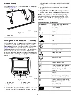
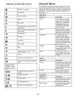
Страница 26: ...s this button to access the InfoCenter menus You can use it to back out of any menu you are currently using Middle Button use this button to scroll down menus Right Button use this button to open a menu where a right arrow indicates additional content Note The purpose of each button may change depending on what is required at the time Each button is labeled with an icon displaying its current func...

Страница 27: ...nual or your Authorized Toro Distributor for more information on the Faults menu and the information contained there Service The Service menu contains information on the machine such as hours of use counters and other similar numbers Diagnostics The Diagnostics menu displays the state of each machine switch sensor and control output You can use this to troubleshoot certain issues as it will quickl...

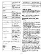
Страница 28: ...us Lists the machine communication bus status Protected Menus There are 5 operating configuration settings that are adjustable within the Settings Menu of the InfoCenter Blade Count Mow Speed Height of Cut HOC F Reel RPM and R Reel RPM These settings can be locked by using the Protected Menu Note At the time of delivery the initial password code is programmed by your distributor Accessing the Prot...

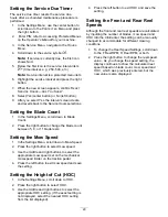
Страница 29: ...ls Setting the Mow Speed 1 In the Settings Menu scroll down to Mow Speed 2 Press the right button to select mow speed 3 Use the middle and right buttons to select the appropriate mow speed set on the mechanical mow speed limiter on the traction pedal 4 Press the left button to exit mow speed and save the setting Setting the Height of Cut HOC 1 In the Settings Menu scroll down to HOC 2 Press the ri...

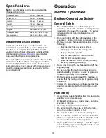
Страница 30: ...r with the safe operation of the equipment operator controls and safety signs Before you leave the operator s position do the following Park the machine on a level surface Disengage and lower the cutting units Engage the parking brake Shut off the engine and remove the key Wait for all movement to stop Allow the machine to cool before adjusting servicing cleaning or storing it Know how to stop the...

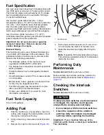
Страница 31: ... hoses gaskets in contact with fuel as they may be degraded over time Fuel filter plugging may be expected for a time after converting to biodiesel blended Contact your distributor if you wish for more information on biodiesel Fuel Tank Capacity 53 L 14 US gallons Adding Fuel 1 Park the machine on a level surface lower the cutting units engage the parking brake shut off the engine and remove the k...

Страница 32: ...eed All 8 spacers moved to the top of the mow speed control With the engine at high idle proceed forward with the mow speed control stop engaged and ride the brake for 15 seconds Proceed backward at full reverse speed and ride the brake for 15 seconds Repeat this 5 times waiting 1 minute between each forward and reverse cycle to avoid overheating the brakes An adjustment to the brakes may be requi...

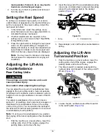
Страница 33: ... cutting units to help compensate for different turf conditions and to maintain a uniform height of cut in rough conditions or in areas of thatch buildup You adjust counterbalance force of each torsion spring to 1 of 4 settings Each increment increases or decreases the counterbalance force on the cutting unit by 2 3 kg 5 lb You can position the springs at the back side of the first spring actuator...

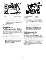
Страница 34: ... 1 Turf compensation spring 3 Spring rod 2 Hairpin 4 Hex nuts 2 Tighten the hex nuts on the front end of the spring rod until the compressed length of the spring is 15 9 cm 6 25 inches refer to Figure 53 Note When operating on rough terrain decrease the spring length by 13 mm 1 2 inch Ground following will be slightly decreased Note The turf compensation setting will need to be reset if the HOC se...

Страница 35: ...ransport lever to the TRANSPORT position Be careful when driving between objects so you do not accidentally damage the machine or cutting units Use extra care when operating the machine on slopes Drive slowly and avoid sharp turns on slopes to prevent rollovers Lower the cutting units when going downhill for steering control After Operation After Operation Safety General Safety Park the machine on...

Страница 36: ...ecause internal transmission damage may occur The bypass valve must be open whenever you push or tow the machine 1 The bypass valve is located on the left side of the hydrostat Figure 57 Rotate the bolt 1 1 2 turns to open and allow fluid to bypass internally Note You can now move the machine slowly without damaging the transmission g003995 Figure 57 1 Bypass valve 2 Close the bypass valve before ...

Страница 37: ...erous and such use could void the product warranty Recommended Maintenance Schedule s Maintenance Service Interval Maintenance Procedure After the first hour Torque the wheel lug nuts to 94 to 122 N m 70 to 90 ft lb After the first 10 hours Torque the wheel lug nuts to 94 to 122 N m 70 to 90 ft lb After the first 50 hours Change the engine oil and filter Check the engine speed idle and full thrott...

Страница 38: ...native fluid replace the return hydraulic filter and charge hydraulic filter If you are not using the recommended hydraulic fluid or have ever filled the reservoir with an alternative fluid change the hydraulic fluid Pack the rear wheel bearings 2 wheel drive machines only Adjust the engine valves refer to the engine owner s manual Every 1 000 hours If you are using the recommended hydraulic fluid...

Страница 39: ...ment operation Check the reel to bedknife adjustment Check the height of cut adjustment Check all grease fittings for lubrication 3 Touch up damaged paint Wash the machine 1 Check the glow plug and injector nozzles if hard starting excess smoke or rough running is noted 2 Check with the engine running and the oil at operating temperature 3 Immediately after every washing regardless of the interval...

Страница 40: ...Wait for the engine to cool Opening the Hood 1 Release the 2 hood latches Figure 58 g369009 Figure 58 1 Hood latch 2 2 Rotate open the hood Closing the Hood 1 Carefully rotate the hood closed Figure 59 g369219 Figure 59 1 Hood latch 2 2 Secure the hood with the 2 hood latches Opening the Screen 1 Remove the ball pin from the screen latch Figure 60 g378175 Figure 60 1 Ball pin 2 Screen latch 2 Unla...

Страница 41: ... rod guide plate Figure 63 g369008 Figure 63 1 Prop rod 2 Rod guide plate Lowering the Seat 1 Rotate the seat slightly and lift the prop rod out of the dent of the seat support slot Figure 64 g375779 Figure 64 1 Prop rod 2 Rod guide plate 2 Carefully lower the seat until it latches securely Jacking Point Locations Note Support the machine with jack stands whenever you work under the machine refer ...

Страница 42: ... 50 hours and immediately after every washing Grease Specification No 2 lithium grease 1 Prepare the machine for maintenance refer to Preparing for Maintenance page 40 2 Open the hood refer to Opening the Hood page 40 3 The lubricate the machine at the fittings at the locations as follows Pump driveshaft U joint 3 Figure 66 Note The pump driveshaft is located Under the hood g003962 Figure 66 Cutti...

Страница 43: ...rm pivot shaft 1 each Figure 69 g004157 Figure 69 Rear axle tie rod 2 Figure 70 g003987 Figure 70 Axle steering pivot 1 Figure 71 g004169 Figure 71 Steering cylinder ball joints 2 Figure 72 g003966 Figure 72 Brake pedal 1 Figure 73 g011615 Figure 73 4 Close and latch the hood refer to Closing the Hood page 40 43 ...

Страница 44: ...into the intake when the filter is removed 3 Remove and replace the filter Figure 75 Cleaning of the used element is not recommended due to the possibility of damage to the filter media Inspect the new filter for shipping damage checking the sealing end of the filter and the body Do not use a damaged element Insert the new filter by applying pressure to the outer rim of the element to seat it in t...

Страница 45: ...til the level reaches the Full mark on dipstick g004134 Figure 77 1 Oil fill cap Important Do not overfill Be sure to keep the engine oil level between the upper and lower limits on the oil gauge Engine failure may occur as a result of over filling or under filling the engine oil 6 Install the oil fill cap and close the hood Servicing the Engine Oil and Filter Change the engine oil and filter init...

Страница 46: ...onditions diesel fuel and fuel vapors are highly flammable and explosive A fire or explosion from fuel can burn you and others and can cause property damage Use a funnel and fill the fuel tank outdoors in an open area when the engine is off and is cold Wipe up any fuel that spills Do not fill the fuel tank completely full Add fuel to the fuel tank until the level is 6 to 13 mm 1 4 to 1 2 inch belo...

Страница 47: ...od page 40 4 Open the air bleed screw on the fuel injection pump Figure 81 g008891 Figure 81 1 Fuel injection pump bleed screw 5 Turn the key in the ignition switch to the ON position The electric fuel pump runs forcing air out around the air bleed screw Note Leave the key in the ON position until a solid stream of fuel flows out around the screw 6 Tighten the screw and turn the ignition key to OF...

Страница 48: ...s Before storage Drain and clean the fuel tank if the fuel system becomes contaminated or if the machine is to be stored for an extended period Use clean fuel to flush out the tank 1 Prepare the machine for maintenance refer to Preparing for Maintenance page 40 2 Align a drain container under the drain valve at the bottom of the fuel tank Figure 83 g369818 Figure 83 1 Drain valve bottom of the fue...

Страница 49: ...the positive terminal first and the negative last Charge the battery in an open well ventilated area away from sparks and flames Unplug the charger before connecting or disconnecting the battery Wear protective clothing and use insulated tools Disconnecting the Battery DANGER Battery electrolyte contains sulfuric acid which is fatal if consumed and causes severe burns Do not drink electrolyte and ...

Страница 50: ...y 1 Disconnect the battery refer to Disconnecting the Battery page 49 2 Connect a 3 to 4 A battery charger to the battery posts 3 Charge the battery at a rate of 3 to 4 A for 4 to 8 hours 4 When the battery is charged disconnect the charger from the electrical outlet and battery posts 5 Connect the battery refer to Connecting the Battery page 50 Servicing the Battery Service Interval Every 50 hour...

Страница 51: ... arm cover 4 Assemble the control arm cover to the control arm and secure the cover with the 2 latches Replacing the Telematic Fuse 1 Prepare the machine for maintenance refer to Preparing for Maintenance page 40 2 Unlatch and tilt seat refer to Tilting the Seat page 41 3 Remove the cap from the in line fuse holder labeled 10 A FUSE TELEMATIC PWR Figure 89 g378242 Figure 89 1 Cap 3 Fuse holder lab...

Страница 52: ...n the NEUTRAL position If the machine moves adjust traction pump as follows 1 Prepare the machine for maintenance refer to Preparing for Maintenance page 40 2 Jack up the front of the machine until the both front tires are off the ground and support the machine with jack stands refer to Jacking Point Locations page 41 and Specifications page 30 3 From the bottom of the machine and at the right sid...

Страница 53: ...center distance 2 6 mm 1 4 inch or less than the rear of the tire 4 If the measurement is greater than 6 mm 1 4 inch adjust the rear wheel toe in refer to Adjusting the Rear Wheel Toe in page 53 Adjusting the Rear Wheel Toe in 1 Loosen the jam nut on each end of the tie rod Figure 92 Note The end of the tie rod with the external groove is a left hand thread g004136 Figure 92 1 Jam nut 3 Wrench fla...

Страница 54: ...oolant manufacturers may dye extended life coolant in one of the following colors red pink orange yellow blue teal violet and green Use coolant that meets the specifications in the Extended Life Coolant Standards Table Extended Life Coolant Standards ATSM International SAE International D3306 and D4985 J1034 J814 and 1941 Important Coolant concentration should be a 50 50 mixture of coolant to wate...

Страница 55: ...stem Service Interval Before each use or daily More frequently in dirty operating conditions Every 100 hours Inspect the cooling system hoses Every 2 years Flush and replace the cooling system fluid 1 Prepare the machine for maintenance refer to Preparing for Maintenance page 40 2 Open the hood refer to Opening the Hood page 40 3 Thoroughly clean all debris out of the engine area 4 Close and latch...

Страница 56: ... the distance the brake pedal moves before you feel braking resistance g026816 Figure 97 1 Free travel Note Use the wheel motor backlash to rock the drums back and forth to ensure that the drums are free prior to and after adjustment 1 To reduce free travel of the brake pedals tighten the brakes by loosening the front nut on the threaded end of the brake cable Figure 98 g011616 Figure 98 1 Brake c...

Страница 57: ...rs Check the condition and tension of the belts Figure 100 after every 100 operating hours 1 Park the machine on a level surface lower the cutting units engage the parking brake shut off the engine and remove the key 2 Open the hood refer to Opening the Hood page 40 3 Check the condition of the alternator belt Note Replace a worn or damaged belt 4 Check the belt tension Note Belt tension is correc...

Страница 58: ...tions so use products only from reputable manufacturers who will stand behind their recommendation High Viscosity Index Low Pour Point Anti wear Hydraulic Fluid ISO VG 46 Material Properties Viscosity ASTM D445 cSt 40 C 104 F 44 to 48 High Viscosity Index Low Pour Point Anti wear Hydraulic Fluid ISO VG 46 cont d Viscosity Index ASTM D2270 140 or higher Pour Point ASTM D97 37 C to 45 C 34 F to 49 F...

Страница 59: ...urs If you are using the recommended hydraulic fluid replace the return hydraulic filter and charge hydraulic filter Every 800 hours If you are not using the recommended hydraulic fluid or have ever filled the reservoir with an alternative fluid replace the return hydraulic filter and charge hydraulic filter Important Use of any other filters may void the warranty on some components Changing the R...

Страница 60: ...lean the filter mounting area of the filter head 6 Apply a thin coat of the specified hydraulic fluid to the gasket of the new charge filter 7 Thread the filter onto the filter head by hand until the gasket contacts the mounting surface then rotate the filter an additional 1 2 turn 8 Lower and latch the seat refer to Lowering the Seat page 41 Checking for Leaks 1 Start the engine and run it for 2 ...

Страница 61: ...nife can break and a piece could be thrown toward you or bystanders resulting in serious personal injury or death Inspect the blades and bedknives periodically for excessive wear or damage Use care when checking the blades Wear gloves and use caution when servicing them Only replace or backlap the blades and bedknives never straighten or weld them On machines with multiple cutting units take care ...

Страница 62: ... to start the backlapping operation on the designated reels 3 Apply lapping compound with a long handled brush DANGER Contacting the cutting units when they are moving could cause personal injury To avoid personal injury be certain that you are clear of the cutting units before proceeding Important Never use a short handled brush 4 If the reels stall or become erratic while backlapping select a hi...

Страница 63: ...e across the front face of the bedknife after lapping Note This removes any burrs or rough edges that may have built up on the cutting edge Chassis Maintenance Inspecting the Seat Belt Service Interval Before each use or daily 1 Inspect the seat belt for wear cuts and other damage Replace the seat belt s if any component does not operate properly 2 Clean the seat belt as necessary 63 ...

Страница 64: ...ou may use a rag when washing the machine Important Do not use brackish or reclaimed water to clean the machine Important Do not use power washing equipment to wash the machine Power washing equipment may damage the electrical system loosen important decals or wash away necessary grease at friction points Avoid excessive use of water near the control panel engine and battery Important Do not wash ...

Страница 65: ...h a wire brush and baking soda solution C Coat the cable terminals and battery posts with Grafo 112X skin over grease Toro Part No 505 47 or petroleum jelly to prevent corrosion D Slowly charge the battery every 60 days for 24 hours to prevent lead sulfation of the battery Preparing the Engine 1 Drain the engine oil from the oil pan and install the drain plug 2 Remove and discard the oil filter In...

Страница 66: ... for marketing purposes Retention of your Personal Information Toro will keep your personal information as long as it is relevant for the above purposes and in accordance with legal requirements For more information about applicable retention periods please contact legal toro com Toro s Commitment to Security Your personal information may be processed in the US or another country which may have le...

Страница 67: ...to restaurants grocery stores hotels schools and hospitals and on a wide variety of products Additionally some online and mail order retailers provide Prop 65 warnings on their websites or in catalogs How do the California warnings compare to federal limits Prop 65 standards are often more stringent than federal and international standards There are various substances that require a Prop 65 warnin...

Страница 68: ......
Отзывы: