

57
GTS 200
Cylinder and Bearings
Check Plain or DU
Bearings
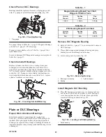
Bearings should be replaced if scored or if plug gauge will
enter. Try gauge at several locations in bearing, Fig. 140.
1
Fig. 140 – Checking Bearing
1.
Plug gauge
See gauge listing in Table No. 1, page 57, Magneto Bearings,
or Table No. 2, page 57, PTO Bearings.
If gauge is not available, refer to Table No. 5, page 58 for
reject dimensions.
Scored or damaged DU
magneto bearings can be replaced,
Table No. 1, page 57.
Check Camshaft Bearings
Replace cylinder, crankcase cover, or sump if cam gear
bearings are worn more than than shown in Table No. 6,
page 58. If specified plug gauge can be inserted in bearing
1/4” (6.35mm) or more, replace cylinder, crankcase cover or
sump, Fig. 141. If gauge is not available, and bearings are
worn larger than dimensions shown in Table No. 6, replace
cylinder, crankcase cover or sump.
Fig. 141 – Checking Camshaft Bearing
Plain or DU
Bearings
Repair Worn Aluminum Bearings
Select tools needed to repair magneto bearing from
Table No. 1. Remove and discard oil seal for bearing to be
repaired. Place pilot guide bushing in bearing opposite of
bearing to be repaired. Have flange of bushing on inside of
crankcase. Replace sump if sump crankshaft bearing is worn
or damaged.
Table No. 1
Magneto Bearing Repair Tool Chart
Briggs & Stratton Tools
Cylinder
Support
Bushing
Driver
Plug
Gauge
19123
19124
19166
Table No. 2
PTO Bearing Repair Tool Chart
Cylinder
Support
Bushing
Driver
Plug
Gauge
N/A
N/A
19375
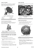
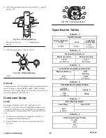
Remove DU
Magneto Bearing
1. Refer to Table No. 1, page 57, for tools required to remove
DU
bearings.
2. Place cylinder support under magneto bearing and place
bushing driver down through worn bearing.
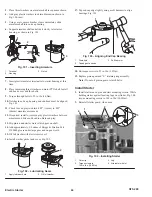
3. Press bearing out of cylinder, Fig. 142.
1
ÎÎÎ
ÎÎÎ
ÏÏÏ
ÏÏÏ
ÏÏÏ
ÏÏÏÏ
ÏÏÏÏ
ÏÏÏÏ
3
2
Fig. 142 – Removing Bearing
1.
Bushing driver bearing
2.
Bearing
3.
Cylinder support
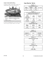
Install Magneto DU
Bushing
1. Place DU bearing on cylinder or cover bearing with oil
hole in line with oil hole in cylinder or cover bearing. If
cover bearing does not have oil hole, place split (when
present) of bearing as shown in Fig. 143.
1
Fig. 143 – Locating and Staking Bearing
1.
Split in bearing