


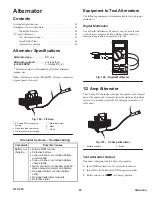

44
GTS 200
Electric Starter
3. Place thrust washers on armature shaft in sequence shown.
4. Add gray plastic washers to obtain dimension shown in
Fig. 100, inset.
5. Using care to ensure brushes clear commutator, slide
armature shaft into end cap bearing.
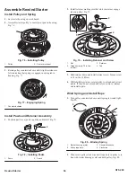
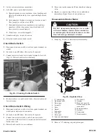
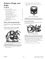
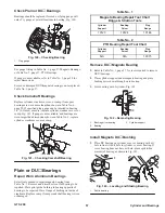
6. Support armature shaft and slide it slowly into starter
housing, as shown in Fig. 101.
1
2
3
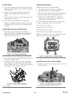
Fig. 101 – Inserting Armature
1.
Terminal
2.
Housing
3.
Notch
7. Insert plastic insulator terminal into starter housing at this
time.
8. Place remaining thrust washers on motor PTO shaft. Install
end head cover and thru bolts.
9. Torque through bolts to 25 in. lbs (3.0Nm).
10. Notches in end cap, housing and end head must be aligned,
Fig. 101.
11. Check for end play to obtain .005” (13mm) to .025”
(64mm) armature movement.
12. If required, install or remove gray plastic washers between
armature and drive end head to obtain end play.
13. Slip pinion and starter motor clutch gear on shaft.
14. Add approximately 3/4 ounce of Briggs & Stratton Part
#100060 grease under large gear and on gear teeth.
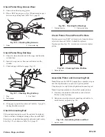
15. Oil felt washer with electric motor oil.
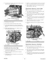
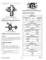
16. Install washer, gasket and cover, Fig. 102.
1
1
2
Fig. 102 – Lubricating Gears
1.
Apply lubricant here
2.
Oil felt washer
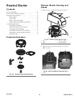
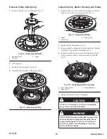
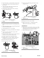
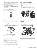
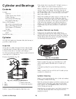
17. Tap end cap edge lightly using a soft hammer to align
bearings, Fig. 103.
1
3
2
Fig. 103 – Aligning End Cap Bearing
1.
Drain hole
2.
Tap edge of end cap
3.
Soft hammer
18. Re-torque screws to 25 in. lbs. (3.0Nm).
19. Replace pinion gear and “E” retaining ring assembly.
Note: Do not oil pinion gear or clutch helix.
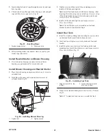
Install Starter
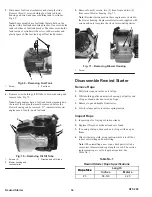
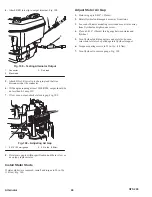
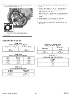
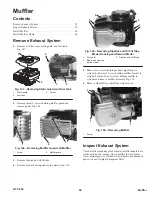
1. Install starter on engine and start mounting screws. While
holding starter against locating lugs on cylinder, Fig. 104,
torque mounting screws to 140 in. lbs. (16.0Nm).
2. Reinstall starter guard, when used.
1
2
3
4
Fig. 104 – Installing Starter
1.
Wire clip
2.
Torque screws to
140 in. lbs. (16.0Nm)
3.
Lug
4.
Alternator wire(s)