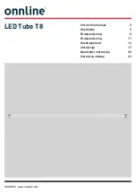
background image

17

2

1

m–5662

Figure 25

1.

Right Center Deck Cover

2.

Left Center Deck Cover

3. Remove the plug on the side of the gearbox. The fluid

level must be up to the side hole in the gearbox
(Fig 26).

4. If fluid is needed, remove the top plug from the

gearbox. Add SAE E.P. 90 wt. gear oil into the top
hole in the gearbox. It is full when it runs out the side
hole.

5. Install the top and side plugs using pipe sealant

(Fig 26).

m–5661

1

3

2

Figure 26

1.

Top plug

2.

Side plug

3.

Gearbox

6. Install both center deck covers onto the deck with

fasteners (Fig. 25).

Replacing the Deck Belt

Squealing when the belt is rotating, blades slipping when
cutting grass, frayed belt edges, burn marks and cracks are
signs of a worn deck belt. Replace the deck belt if any of
these conditions are evident.

1. Loosen the fasteners holding the left and right center

deck covers and remove both center deck covers
(Fig. 27).

2. Remove the flange screws holding the left and right

covers to the deck and remove both covers (Fig. 27).

3

4

2

1

m–5662

Figure 27

1.

Right Deck Cover

2.

Right Center Deck Cover

3.

Left Center Deck Cover

4.

Left Deck Cover

3. Lift the idler pulley and remove the drive belt. Refer

to Replacing the Drive Belt on page 18.

4. Install the new deck belt around the three spindle

pulleys, gearbox output pulley and deck idler pulley
(Fig. 28).

5. Reconnect the deck idler arm spring (Fig. 28).

4

6

2

m–2563

1

3

5

Figure 28

Top View

1.

Deck Belt

2.

Deck Idler Arm Spring

3.

Deck Idler Pulley

4.

Spindle Pulley (3)

5.

Gearbox Output Pulley

6.

Idler Arm

Содержание Groundsmaster 120

Страница 1: ...Operator s Manual English GB Form No 3327 512 44 Mower Groundsmaster 120 Attachment Model No 30544TE Serial No 22000001 and Up...

Страница 2: ...uct damage Although Toro designs and produces safe products you are responsible for operating the product properly and safely Whenever you need service genuine Toro parts or additional information con...

Страница 3: ...3 Slope Chart...

Страница 4: ...4...

Страница 5: ...93 7273 1 Thrown object hazard keep bystanders away 2 Cutting dismemberment hazard of hands or feet stay away from rotating blades and moving parts Part No 93 7824 1 Thrown object hazard keep bystande...

Страница 6: ...alling the front baffle Cap Screw 3 8 x 1 3 4 in Locknut 3 8 in Shim Flange Bolt 3 8 x 7 8 in Flat Washer 4 4 2 4 4 Install carrier frame to traction unit Drive Belt 1 Mount to cutting unit and tracti...

Страница 7: ...ower and flush with left edge of mower Fig 4 3 Clamp the baffle in place m 5724 5 1 3 4 2 2 Figure 3 1 Front view of deck 2 Front baffle 3 13 mm 1 2 in 4 26 mm 1 in 5 Side discharge opening 4 Using th...

Страница 8: ...n and locknuts 3 8 in to 27 33 ft lb 37 45 N m Fig 5 1 2 m 2560 6 3 7 5 4 Figure 5 1 Cap Screw 3 8 x 1 3 4 in 2 Shim 3 Flange Bolt 3 8 x 7 8 in 4 Flat Washer 5 Carrier Frame 6 Traction Unit Frame 7 Lo...

Страница 9: ...and disengages power to the electric clutch Engaging the PTO 1 Release the parking brake 2 Release pressure on the traction pedal to stop movement 3 To engage lift cover and move the PTO switch to the...

Страница 10: ...11 Stop the engine before adjusting the height of cut Note All four pins must be in the same hole location for even cutting 8 9 1 3 5 7 2 4 6 m 2567 Figure 11 1 1 in 25 mm Cut Height 2 1 1 2 in 38 mm...

Страница 11: ...r than normal or if it contains a high degree of moisture raise the cutting height higher than usual and cut the grass at this setting Then cut the grass again using the lower normal setting When Stop...

Страница 12: ...ce Set the wire aside so that it does not accidentally contact the spark plug Cutting Blade Service To ensure a superior quality of cut keep the blades sharp For convenient sharpening and replacement...

Страница 13: ...s forward 3 Measure from a level surface to the cutting edge of the blades at the same position as in step 1 above The difference between the dimensions obtained in steps 1 and 2 must not exceed 1 8 i...

Страница 14: ...15 Torque the blade bolt to 85 110 ft lb 115 149 N m Correcting Cutting Unit Mismatch If one cutter blade cuts lower than the other correct as follows 1 Stop the engine remove the key and disconnect...

Страница 15: ...s from the bottom of the mounting tube to the top to lower the front of the mower Fig 20 5 Check the side to side leveling of the cutting unit m 2559 2 1 1 3 Figure 20 1 Thrust Washer 2 Carrier Frame...

Страница 16: ...aintenance Schedule on page 12 Grease with No 2 general purpose lithium base or molybdenum base grease 1 Grease the fittings on the three spindle pulley bearings Fig 23 Note You can access the spindle...

Страница 17: ...s burn marks and cracks are signs of a worn deck belt Replace the deck belt if any of these conditions are evident 1 Loosen the fasteners holding the left and right center deck covers and remove both...

Страница 18: ...29 1 2 3 m 5662 Figure 29 1 Fastener 2 Left Center Deck Cover 3 Gearbox Input Pulley 2 Hold the idler pulley up and install the new drive belt onto the traction unit output pulley and gearbox input pu...

Страница 19: ...n block up the front of the mower with jack stands 2 Remove the linchpin and thrust washer s from the top of the castor wheel fork Fig 33 3 Pull the castor wheel fork out of the mounting tube leaving...

Страница 20: ...r worn parts Fig 35 5 Install the washers on the outsides of the bushings then install the castor wheel into the castor fork and secure with the wheel bolt and locknut Tighten the locknut until the sp...

Страница 21: ...Dealer 7 Store the machine in a clean dry garage or storage area Cover the machine to protect it and keep it clean Troubleshooting PROBLEM POSSIBLE CAUSES CORRECTIVE ACTION Abnormal vibration 1 Cuttin...

Страница 22: ...belt and check traction unit idler pulley idler arm and spring for correct position and function 3 Deck belt is worn loose or broken 3 Install new deck belt 4 Deck idler pulley tension is too loose 4...

Страница 23: ...23...

Страница 24: ...24...

Отзывы: