8
Grounding the Communication Cable
The lightning arrester (Toro P/N DEC-SG-LINE) is required to protect the decoder module from lightning. Without
lightning arresters, decoders are vulnerable to lightning damage. In order for these arresters to discharge lightning energy
efficiently, they must be properly grounded. To be effective, a resistance of 10 Ohms or less must be achieved at each earth
ground point.
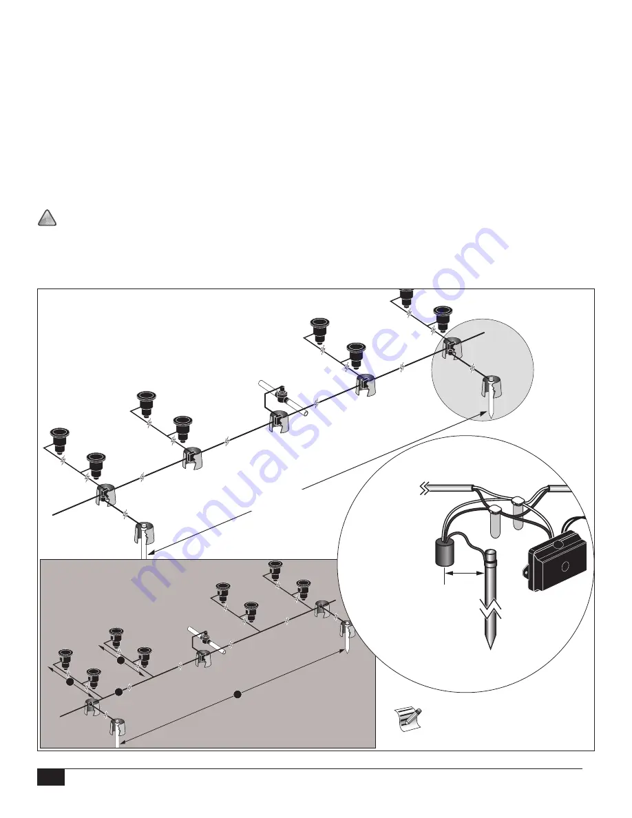
Figure 5
illustrates the proper grounding and wiring of the arrester.
1. Locate decoder’s power/communication wires (black and white wires).
2. Strip the insulation from lightning arrester’s white wire and connect it to the white wires from the decoder and
controller-to-decoder cable. Use 3M DBR/Y to properly water-proof all wire connections. (See
Figure 5
.)
3. Strip the insulation from lightning arrester’s black wire and connect it to the black wires from the decoder and
controller-to-decoder cable. Use 3M DBR/Y to properly water-proof all wire connections. (See
Figure 5
.)
4. Connect the lightning arrester’s ground wire to the ground rod or plate’s wire. If the ground rod or plate is not pre-
wired, use a 10 AWG bare copper wire. (See
Figure 5
.)
!
IMPORTANT!
If using a ground rod, verify that the straight line distance between the lightning arrester/decoders and
the ground rod is 8' (2.5m) +/– 10%. If using a 3' (1m) ground plate, the straight line distance should be 3' (1m) +/– 10%.
5. If necessary, use ground enhancement material (GEM) to attain a resistance of 10 Ohms or less.
6. Check the system for proper operation.
See Detail A
D
A
B
C
Golf Sprinkler with Decoder
Detail A
8' (2.5m) (+/– 10%) between
the arrester and the ground
rod or 3' (+/– 10%) distance
between arrestor and ground
plate.
Lightning Arrester
Toro P/N
DEC-SG-LINE
Toro Decoder
Module
Maximum of 1000' (300 m) of populated
communication line between ground points
A = 500' (150m) Max
B+C = 500' (150m) Max
D = 1000' (300m) Max
Ensure a maximum of 10 Ohms
resistance for each earth ground.
Figure 5

