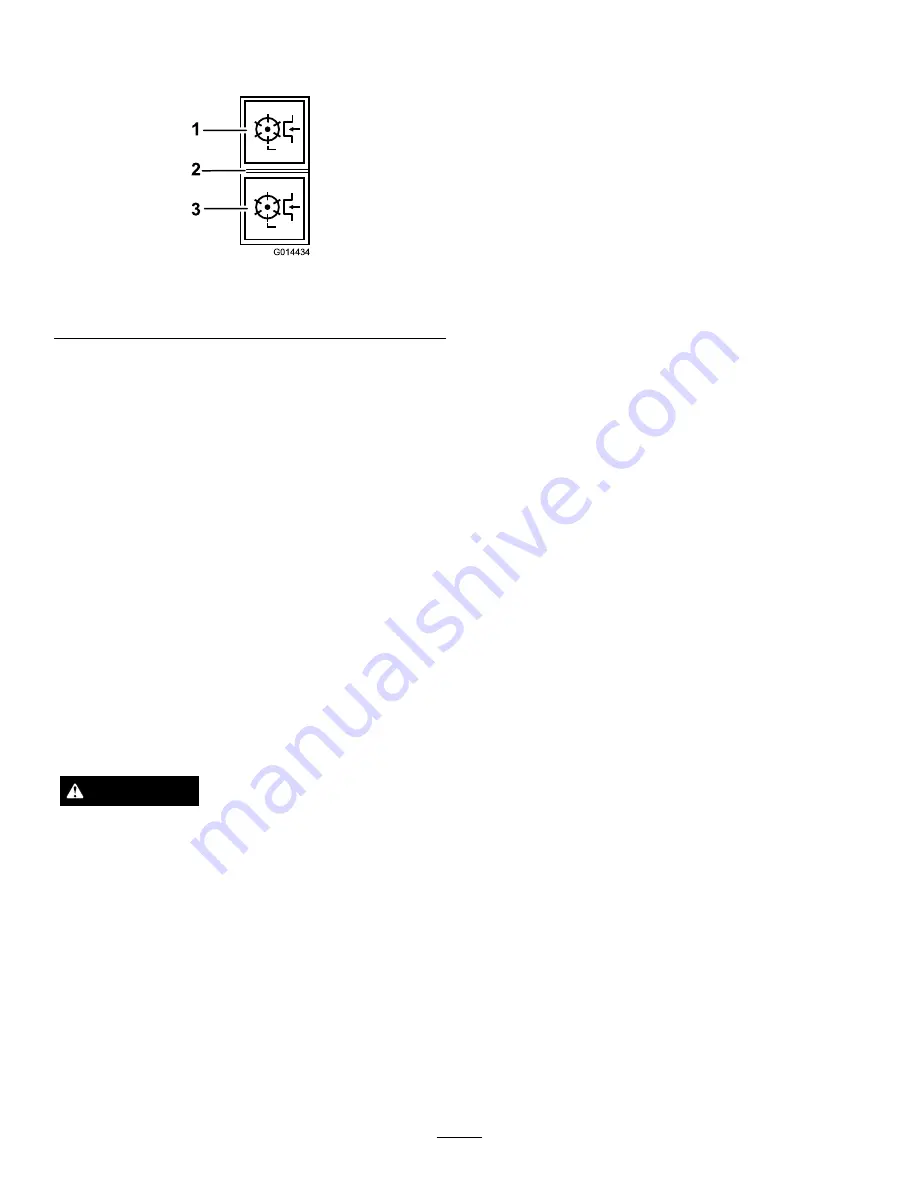
Engaging the Cutterhead
Drive
1
2
3
G014434
Figure 41
1.
Forward
3.
Reverse
2.
Off
The cutterhead drive can be engaged only
when the operator is seated correctly, refer
to Operator Presence Seat Switch (page 44).
Forward rotation cutterhead drive engagement:
Depress the top of the cutterhead drive switch to the
forward position.
Reverse rotation cutterhead drive engagement:
Depress the bottom of the cutterhead drive switch to
the reverse position.
All cutterhead drives disengagement:
Set the switch
to the middle position.
To lower the cutterheads:
The cutterhead drive
switch must be set to forward. Operate the lift control
switch(s) in a downward direction. The cylinder will
drive when the cutterheads are approximately 150mm
(6 inches) above ground level.
Clearing the Cutting Cylinders
WARNING
Never attempt to rotate the cutting cylinders by
hand.
•
There may be some residual pressure in the
hydraulic system which could cause injury
through sudden movement of the cylinder(s)
when the blockage is released.
•
Always wear protective gloves and use a suitable
strong wooden instrument.
•
Ensure that the wooden instrument will fit
between the blades and through the cylinder
and is long enough to provide sufficient
leverage to release the blockage.
1. Stop the machine on level ground.
2. Apply the parking brake and disengage all drives.
3. Lower the cutting units to the ground or securely
lock in the designated transport positions.
4. Stop the engine and remove the ignition key to
isolate all power sources and check that they are
stopped.
5. Release all stored energy devices.
6. Check that all moving parts are stationary.
7. Using a suitable strong wooden instrument,
remove the blockage. Make sure that the wooden
instrument is properly supported in the cylinder and
avoid the use of excessive force to prevent damage.
8. Ensure that the wooden instrument is removed
from the cutting cylinder before restarting the
power source.
9. Repair or adjust the cylinder if required.
Using Weight
Transfer/Traction Assistance
A variable hydraulic weight transfer system is provided
for improving tyre grip with the grass surface - traction
assistance.
Hydraulic pressure in the cutterheads lift system
provides a lifting force which reduces cutterheads
weight on the ground and transfers the weight as a
downward force onto the mower’s tyres. This action is
known as weight transfer.
To engage weight transfer:
The amount of weight
transfer can be varied to suit operating conditions by
rotating the weight transfer hand wheel as follows:
1. Release the valve lock nut 1/2 turn anti-clockwise
and hold.
2. Rotate the valve hand wheel.
•
Anti-clockwise to reduce weight transfer.
•
Clockwise to increase weight transfer.
3. Tighten the nut.
28
Содержание CT2120 30655
Страница 55: ...Schematics Showing Beacon Lights Aux Power Connector g014756 55 ...
Страница 61: ...Notes 61 ...
Страница 62: ...Notes 62 ...


