


2
All Rights Reserved
Printed in the USA
2002 by The Toro Company
8111 Lyndale Avenue South
Bloomington, MN 55420-1196
Contents
Page
Introduction
2
. . . . . . . . . . . . . . . . . . . . . . . . . . . . . . . . .
Safety and Instruction Decals
3
. . . . . . . . . . . . . . . . .
Setup
4
. . . . . . . . . . . . . . . . . . . . . . . . . . . . . . . . . . . . . .
Loose Parts
4
. . . . . . . . . . . . . . . . . . . . . . . . . . . . . . .
Preparing the Mower
4
. . . . . . . . . . . . . . . . . . . . . . .
Preparing the Tractor
6
. . . . . . . . . . . . . . . . . . . . . . .
Installing the Mower
7
. . . . . . . . . . . . . . . . . . . . . . .
Adjusting the Transport Height
8
. . . . . . . . . . . . . . .
Leveling the Mower Side-to-Side
8
. . . . . . . . . . . . .
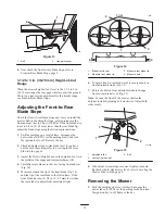
Adjusting the Front-to-Rear Blade Slope
9
. . . . . . . .
Removing the Mower
9
. . . . . . . . . . . . . . . . . . . . . . .
Operation
10
. . . . . . . . . . . . . . . . . . . . . . . . . . . . . . . . . . .
Side Discharge
10
. . . . . . . . . . . . . . . . . . . . . . . . . . . .
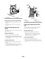
Operating the Power Take Off (PTO)
10
. . . . . . . . . .
Using the Attachment Lift Lever
11
. . . . . . . . . . . . . .
Using the Attachment Power Lift
11
. . . . . . . . . . . . .
Adjusting Dial-A-Height
12
. . . . . . . . . . . . . . . . . . . .
Adjusting Anti-Scalp Wheels
12
. . . . . . . . . . . . . . . . .
Tips for Mowing Grass
13
. . . . . . . . . . . . . . . . . . . . .
Maintenance
14
. . . . . . . . . . . . . . . . . . . . . . . . . . . . . . . . .
Recommended Maintenance Schedule
14
. . . . . . . . .
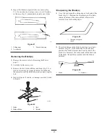
Servicing the Cutting Blades
14
. . . . . . . . . . . . . . . . .
Greasing and Lubrication
16
. . . . . . . . . . . . . . . . . . . .
Servicing the Blade Drive Belt
16
. . . . . . . . . . . . . . .
Servicing the Power Take Off (PTO) Belt
17
. . . . . . .
Washing the Underside of Mower
17
. . . . . . . . . . . . .
Storage
18
. . . . . . . . . . . . . . . . . . . . . . . . . . . . . . . . . .
Troubleshooting
19
. . . . . . . . . . . . . . . . . . . . . . . . . . . . . .
Introduction
Read this manual carefully to learn how to operate and
maintain your product properly. The information in this
manual can help you and others avoid injury and product
damage. Although Toro designs and produces safe
products, you are responsible for operating the product
properly and safely.
Whenever you need service, genuine Toro parts, or
additional information, contact an Authorized Service
Dealer or Toro Customer Service and have the model and
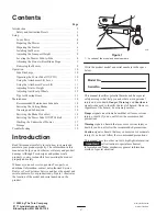
serial numbers of your product ready. Figure 1 illustrates
the location of the model and serial numbers on the
product.
1
2371
Figure 1
1.
Location of the model and serial numbers
Write the product model and serial numbers in the space
below:
Model No.
Serial No.
This manual identifies potential hazards and has special
safety messages that help you and others avoid personal
injury and even death. Danger, Warning, and Caution are
signal words used to identify the level of hazard. However,
regardless of the hazard, be extremely careful.
Danger signals an extreme hazard that will cause serious
injury or death if you do not follow the recommended
precautions.
Warning signals a hazard that may cause serious injury or
death if you do not follow the recommended precautions.
Caution signals a hazard that may cause minor or moderate
injury if you do not follow the recommended precautions.
This manual uses two other words to highlight information.
Important
calls attention to special mechanical
information and Note: emphasizes general information
worthy of special attention.
Содержание 78281
Страница 20: ...20 ...


