Toro 22303 Скачать руководство пользователя страница 36

The Toro Dingo

 Product Line Warranty

A One-Year Limited Warranty

Conditions and Products Covered

The Toro Company and its affiliate, Toro Warranty Company,
pursuant to an agreement between them, jointly warrant your Toro
Dingo Product (“Product”) to be free from defects in materials or
workmanship. The following time periods apply from the date the
Product is delivered to the original retail purchaser:

Products

Warranty Period

All traction units and
attachments

1 year or 1000 operational hours,

whichever occurs first

All engines

2 years

Where a warrantable condition exists, we will repair the Product at
no cost to you including diagnosis, labor, and parts.

Instructions for Obtaining Warranty Service

If you think that your Toro Product contains a defect in materials or
workmanship, follow this procedure:

1Contact any Authorized Dingo Service Dealer to arrange

service at their dealership. To locate a dealer convenient to
you, access our website at www.Toro.com. U.S. Customers
may also call 800-348-2424.

2Bring the product and your proof of purchase (sales receipt) to

the Service Dealer.

If for any reason you are dissatisfied with the Service Dealer’s
analysis or with the assistance provided, contact us at:

LCB Customer Service Department
Toro Warranty Company
8111 Lyndale Avenue South
Bloomington, MN  55420-1196
888-577-7466 (U.S. customers)
877-484-9255 (Canada customers)

Owner Responsibilities

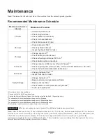
You must maintain your Toro Product by following the maintenance
procedures described in the operator’s manual. Such routine
maintenance, whether performed by a dealer or by you, is at your
expense. Parts scheduled for replacement as required mainte-
nance (“Maintenance Parts”), are warranted for the period of time
up to the scheduled replacement time for that part. Failure to
perform required maintenance and adjustments can be grounds
for disallowing a warranty claim.

Items and Conditions Not Covered

Not all product failures or malfunctions that occur during the
warranty period are defects in materials or workmanship. This
express warranty does not cover the following:

Product failures which result from the use of non-Toro
replacement parts, or from installation and use of add-on,
modified, or unapproved accessories

Product failures which result from failure to perform required
maintenance and/or adjustments

Product failures which result from operating the Product in an
abusive, negligent or reckless manner

Parts subject to consumption through use unless found to be
defective. Examples of parts which are consumed, or used up,
during normal Product operation include, but are not limited to,
digging teeth, tines, spark plugs, tires, tracks, filters, chains,
etc.

Failures caused by outside influence. Items considered to be
outside influence include, but are not limited to, weather,
storage practices, contamination, use of unapproved coolants,
lubricants, additives, or chemicals, etc.

Normal “wear and tear” items. Normal “wear and tear”
includes, but is not limited to, worn painted surfaces, scratched
decals or windows, etc.

Any component covered by a separate manufacturer’s war-
ranty

Pickup and delivery charges

General Conditions

Repair by an Authorized Toro Service Dealer is your sole remedy
under this warranty.

Neither The Toro Company nor Toro Warranty Company is liable
for indirect, incidental or consequential damages in connection
with the use of the Toro Products covered by this warranty,
including any cost or expense of providing substitute equipment or
service during reasonable periods of malfunction or non-use
pending completion of repairs under this warranty.

Some states do not allow exclusions of incidental or consequential
damages, or limitations on how long an implied warranty lasts, so
the above exclusions and limitations may not apply to you.

This warranty gives you specific legal rights, and you may also
have other rights which vary from state to state.

Except for the Emissions warranty referenced below, if applicable,
there is no other express warranty. All implied warranties of
merchantability and fitness for use are limited to the duration of this
express warranty.

Note to California residents: The Emissions Control System on
your Product may be covered by a separate warranty meeting
requirements established by the U.S. Environmental Protection
Agency (EPA) or the California Air Resources Board (CARB). The
hour limitations set forth above do not apply to the Emissions
Control System Warranty. Refer to the California Emission Control
Warranty Statement printed in you operator’s manual or contained
in the engine manufacturer’s documentation for details.

Countries Other than the United States or Canada

Customers who have purchased Toro products exported from the United States or Canada should contact their Toro Distributor (Dealer)
to obtain guarantee policies for your country, province, or state. If for any reason you are dissatisfied with your Distributor’s service or
have difficulty obtaining guarantee information, contact the Toro importer. If all other remedies fail, you may contact us at Toro Warranty
Company.

Part No. 374-0047 Rev. –

Содержание 22303

Страница 1: ...Operator s Manual Domestic English EN Form No 3329 108 Dingo 320 D Dingo Compact Utility Loader Model No 22303 230000001 and Up...

Страница 2: ...acturer Contents Page Introduction 2 Safety 3 Safe Operating Practices 3 Slope Chart 6 Safety and Instruction Decals 7 Assembly 8 Loose Parts 8 Installing the Valve Lever 8 Activating the Battery 9 Pa...

Страница 3: ...ormation and Note emphasizes general information worthy of special attention Safety Improper use or maintenance by the operator or owner can result in injury To reduce the potential for injury comply...

Страница 4: ...vy end Raising the loader arms on a slope will affect the stability of the machine Whenever possible keep the loader arms in the lowered position when on slopes Removing an attachment on a slope will...

Страница 5: ...re explosive Use only an approved container Never remove the fuel tank cap or add fuel when the engine is running Allow the engine to cool before refueling Do not smoke Never refuel the traction unit...

Страница 6: ...6 Slope Chart...

Страница 7: ...ons are easily visible to the operator and are located near any area of potential danger Replace any decal that is damaged or lost 98 9051 99 3157 93 6680 105 8432 98 4682 98 8220 93 6681 1 Cutting di...

Страница 8: ...the normal operating position Loose Parts Note Use the chart below to verify that all parts have been shipped DESCRIPTION QTY USE Traction Unit Valve Lever 1 1 Install valve lever Key 2 Start engine H...

Страница 9: ...re 3 1 Battery cover 2 Bolt 3 Battery 4 Bars 5 Nut 6 Positive cable 7 Negative cable 3 Lift the battery off of the platform Danger Battery electrolyte contains sulfuric acid which is a deadly poison a...

Страница 10: ...t 13 Connect the negative black cable to the negative battery post Fig 3 Note Ensure that the battery cables do not contact any sharp edges or each other 14 Install the battery cover Fig 3 Specificati...

Страница 11: ...hout attachment 7 20 17 Traction unit with counterweight without attachment 5 21 17 Traction unit with an attachment rated with one of the following stability ratings for each slope position A 25 25 2...

Страница 12: ...eparation of the fuel due to lower temperatures Use of summer grade diesel fuel above 20 F 7 C will contribute toward longer life of the fuel pump components Important Do not use kerosene or gasoline...

Страница 13: ...er the loader arms and stop the engine Remove the key 2 Allow the engine to cool 3 Remove the radiator filler cap and check the coolant level Fig 8 The coolant should be up to filler neck 4 If coolant...

Страница 14: ...ge 23 5 Clean the area around the filler neck of the hydraulic tank Fig 9 6 Remove the cap from the filler neck and check the fluid level on the dipstick Fig 9 1 m 4596 2 Figure 9 1 Filler neck cap 2...

Страница 15: ...5 Handle 16 Battery 17 Indicator lights 18 Tow valves You could fall off of the platform and be seriously injured during operation Do not move the control levers unless you are standing with both feet...

Страница 16: ...the slow turtle position to set the auxiliary hydraulics to high speed and the traction drive loader arms and attachment tilt to low speed If you move the speed selector lever while the traction unit...

Страница 17: ...the glow plug light indicate that the glow plugs are on Figure 14 illustrates the four indicator lights 3 1 2 m 4603 4 Figure 14 1 Oil pressure light 2 Battery light 3 Engine temperature light 4 Glow...

Страница 18: ...r to the slow turtle position 2 Lower the loader arms to the ground 3 Turn the ignition key to the stop position Note If the engine has been working hard or is hot let it idle for a minute before stop...

Страница 19: ...The loader arms may lower when in the raised position crushing anyone under them Install the cylinder locks before performing maintenance that requires raised loader arms Warning Installing the Cylin...

Страница 20: ...lip of the attachment receiver plate Fig 18 m 4055 1 2 Figure 18 1 Mount plate 2 Receiver plate 5 Raise the loader arms while tilting back the mount plate at the same time Important The attachment sh...

Страница 21: ...rs Allow the traction unit to cool before touching hydraulic components Do not touch hydraulic fluid spills Caution 7 Push the attachment female connector into the male connector on the traction unit...

Страница 22: ...coolant protection temperature7 Touch up chipped paint 1More often in dusty dirty conditions 2Change oil after the first 50 operating hours 3Change the hydraulic filter and torque the wheel lug nuts a...

Страница 23: ...0 4 Pull the cover off of the traction unit Fig 20 m 4595 1 2 Figure 20 1 Front access cover 2 Locking tabs 5 When finished replace the front access cover and secure it with the two locking tabs Openi...

Страница 24: ...while shining a bright light on the outside of the filter Holes in the filter will appear as bright spots If the filter is damaged discard it otherwise clean it Important Never attempt to clean the s...

Страница 25: ...e clamp and remove the plug Fig 25 6 When the oil has drained completely replace the plug and tighten the clamp Note Dispose of the used oil at a certified recycling center 1 m 4593 2 3 Figure 25 1 Cl...

Страница 26: ...1 2 3 1262 Figure 27 1 Filler caps 2 Lower part of tube 3 Plates 3 If the electrolyte is low add the required amount of distilled water refer to Adding Water to the Battery below Adding Water to the...

Страница 27: ...nd check for leaks 12 Check the fluid level in the hydraulic tank refer to Checking the Hydraulic Fluid page 14 and add fluid to raise the level to the mark on the dipstick Do not over fill the tank 1...

Страница 28: ...tank Fig NO TAG 3 Open the rear access cover refer to Opening the Rear Access Cover page 23 4 Open the drain valve Fig 29 and drain the fuel from the fuel filter into a suitable container and dispose...

Страница 29: ...strated in Figure 31 m 5609 1 2 Figure 31 1 Fuel valve open 2 Fuel valve closed 4 Open the rear access cover refer to Opening the Rear Access Cover page 23 5 Loosen the hose clamp at the fuel filter a...

Страница 30: ...N The starter does not crank 1 The electrical connections are corroded or loose 1 Check the electrical connections for good contact 2 A fuse is blown or loose 2 Correct or replace the fuse 3 The relay...

Страница 31: ...fuel of proper grade for ambient temperature conditions You may need to warm the entire traction unit 16 The ETR solenoid is broken 16 Contact your Authorized Service Dealer The engine starts but does...

Страница 32: ...ized Service Dealer 7 Excessive carbon build up 7 Contact your Authorized Service Dealer 8 Internal wear or damage 8 Contact your Authorized Service Dealer The engine will not idle 1 The fuel tank ven...

Страница 33: ...e Dealer The engine loses power 1 The crankcase oil level is incorrect 1 Fill or drain to the full mark 2 The air cleaner element is dirty 2 Clean or replace 3 Dirt water stale fuel or incorrect fuel...

Страница 34: ...f before starting the engine 2 The engine temperature is low 2 Check the thermostat 3 The glow plugs are inoperative 3 Check the fuse glow plugs and wiring 4 The fuel injection nozzles are damaged 4 C...

Страница 35: ...35...

Страница 36: ...nsumption through use unless found to be defective Examples of parts which are consumed or used up during normal Product operation include but are not limited to digging teeth tines spark plugs tires...

Отзывы: