Toro 22303 Скачать руководство пользователя страница 21

21

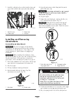
Connecting the Hydraulic Hoses

If the attachment requires hydraulics for operation,
connect the hydraulic hoses as follows:

1. Stop the engine.

2. Move the auxiliary hydraulics lever forward,

backward, and back to neutral to relieve pressure at the
hydraulic couplers.

3. Push the auxiliary hydraulics lever forward into the

detent position.

4. Remove the protective covers from the hydraulic

couplers on the traction unit.

5. Ensure that all foreign matter is cleaned from the

hydraulic connectors.

6. Push the attachment male connector into the female

connector on the traction unit.

Note: When you connect the attachment male connector
first, you will relieve any pressure build up in the
attachment.

Hydraulic fluid escaping under pressure can
penetrate skin and cause injury. Fluid injected
into the skin must be surgically removed within a
few hours by a doctor familiar with this form of
injury or gangrene may result.

Keep your body and hands away from pin hole
leaks or nozzles that eject high pressure
hydraulic fluid.

Use cardboard or paper to find hydraulic leaks,
never use your hands.

Warning

Hydraulic couplers, hydraulic lines/valves, and
hydraulic fluid may be hot.  If you contact hot
components you may be burned.

Wear gloves when operating the hydraulic
couplers.

Allow the traction unit to cool before touching
hydraulic components.

Do not touch hydraulic fluid spills.

Caution

7. Push the attachment female connector into the male

connector on the traction unit.

8. Confirm that the connection is secure by pulling on the

hoses.

9. Move the auxiliary hydraulics lever to neutral.

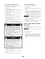
Removing an Attachment

1. Lower the attachment to the ground

2. Stop the engine.

3. Disengage the quick attach pins by turning them to the

outside.

4. If the attachment uses hydraulics, move the auxiliary

hydraulics lever forward, backward, and back to
neutral to relieve pressure at the hydraulic couplers.

5. If the attachment uses hydraulics, slide the collar back

on the hydraulic couplers and disconnect them.

Important


Connect the attachment hoses together to

prevent hydraulic system contamination during storage.

6. Install the protective covers onto the hydraulic

couplers on the traction unit.

7. Start the engine, tilt the mount plate forward, and back

the traction unit away from the attachment.

Securing the Traction Unit for
Transport

When transporting the traction unit on a trailer, always use
the following procedure:

Important


Do not operate or drive the traction unit on

roadways.

1. Lower the loader arms.

2. Stop the engine.

3. Secure the traction unit to the trailer with chains or

straps using the operator platform support openings to
secure the rear of the traction unit and the loader
arms/mount plate to secure the front of the traction
unit.

Содержание 22303

Страница 1: ...Operator s Manual Domestic English EN Form No 3329 108 Dingo 320 D Dingo Compact Utility Loader Model No 22303 230000001 and Up...

Страница 2: ...acturer Contents Page Introduction 2 Safety 3 Safe Operating Practices 3 Slope Chart 6 Safety and Instruction Decals 7 Assembly 8 Loose Parts 8 Installing the Valve Lever 8 Activating the Battery 9 Pa...

Страница 3: ...ormation and Note emphasizes general information worthy of special attention Safety Improper use or maintenance by the operator or owner can result in injury To reduce the potential for injury comply...

Страница 4: ...vy end Raising the loader arms on a slope will affect the stability of the machine Whenever possible keep the loader arms in the lowered position when on slopes Removing an attachment on a slope will...

Страница 5: ...re explosive Use only an approved container Never remove the fuel tank cap or add fuel when the engine is running Allow the engine to cool before refueling Do not smoke Never refuel the traction unit...

Страница 6: ...6 Slope Chart...

Страница 7: ...ons are easily visible to the operator and are located near any area of potential danger Replace any decal that is damaged or lost 98 9051 99 3157 93 6680 105 8432 98 4682 98 8220 93 6681 1 Cutting di...

Страница 8: ...the normal operating position Loose Parts Note Use the chart below to verify that all parts have been shipped DESCRIPTION QTY USE Traction Unit Valve Lever 1 1 Install valve lever Key 2 Start engine H...

Страница 9: ...re 3 1 Battery cover 2 Bolt 3 Battery 4 Bars 5 Nut 6 Positive cable 7 Negative cable 3 Lift the battery off of the platform Danger Battery electrolyte contains sulfuric acid which is a deadly poison a...

Страница 10: ...t 13 Connect the negative black cable to the negative battery post Fig 3 Note Ensure that the battery cables do not contact any sharp edges or each other 14 Install the battery cover Fig 3 Specificati...

Страница 11: ...hout attachment 7 20 17 Traction unit with counterweight without attachment 5 21 17 Traction unit with an attachment rated with one of the following stability ratings for each slope position A 25 25 2...

Страница 12: ...eparation of the fuel due to lower temperatures Use of summer grade diesel fuel above 20 F 7 C will contribute toward longer life of the fuel pump components Important Do not use kerosene or gasoline...

Страница 13: ...er the loader arms and stop the engine Remove the key 2 Allow the engine to cool 3 Remove the radiator filler cap and check the coolant level Fig 8 The coolant should be up to filler neck 4 If coolant...

Страница 14: ...ge 23 5 Clean the area around the filler neck of the hydraulic tank Fig 9 6 Remove the cap from the filler neck and check the fluid level on the dipstick Fig 9 1 m 4596 2 Figure 9 1 Filler neck cap 2...

Страница 15: ...5 Handle 16 Battery 17 Indicator lights 18 Tow valves You could fall off of the platform and be seriously injured during operation Do not move the control levers unless you are standing with both feet...

Страница 16: ...the slow turtle position to set the auxiliary hydraulics to high speed and the traction drive loader arms and attachment tilt to low speed If you move the speed selector lever while the traction unit...

Страница 17: ...the glow plug light indicate that the glow plugs are on Figure 14 illustrates the four indicator lights 3 1 2 m 4603 4 Figure 14 1 Oil pressure light 2 Battery light 3 Engine temperature light 4 Glow...

Страница 18: ...r to the slow turtle position 2 Lower the loader arms to the ground 3 Turn the ignition key to the stop position Note If the engine has been working hard or is hot let it idle for a minute before stop...

Страница 19: ...The loader arms may lower when in the raised position crushing anyone under them Install the cylinder locks before performing maintenance that requires raised loader arms Warning Installing the Cylin...

Страница 20: ...lip of the attachment receiver plate Fig 18 m 4055 1 2 Figure 18 1 Mount plate 2 Receiver plate 5 Raise the loader arms while tilting back the mount plate at the same time Important The attachment sh...

Страница 21: ...rs Allow the traction unit to cool before touching hydraulic components Do not touch hydraulic fluid spills Caution 7 Push the attachment female connector into the male connector on the traction unit...

Страница 22: ...coolant protection temperature7 Touch up chipped paint 1More often in dusty dirty conditions 2Change oil after the first 50 operating hours 3Change the hydraulic filter and torque the wheel lug nuts a...

Страница 23: ...0 4 Pull the cover off of the traction unit Fig 20 m 4595 1 2 Figure 20 1 Front access cover 2 Locking tabs 5 When finished replace the front access cover and secure it with the two locking tabs Openi...

Страница 24: ...while shining a bright light on the outside of the filter Holes in the filter will appear as bright spots If the filter is damaged discard it otherwise clean it Important Never attempt to clean the s...

Страница 25: ...e clamp and remove the plug Fig 25 6 When the oil has drained completely replace the plug and tighten the clamp Note Dispose of the used oil at a certified recycling center 1 m 4593 2 3 Figure 25 1 Cl...

Страница 26: ...1 2 3 1262 Figure 27 1 Filler caps 2 Lower part of tube 3 Plates 3 If the electrolyte is low add the required amount of distilled water refer to Adding Water to the Battery below Adding Water to the...

Страница 27: ...nd check for leaks 12 Check the fluid level in the hydraulic tank refer to Checking the Hydraulic Fluid page 14 and add fluid to raise the level to the mark on the dipstick Do not over fill the tank 1...

Страница 28: ...tank Fig NO TAG 3 Open the rear access cover refer to Opening the Rear Access Cover page 23 4 Open the drain valve Fig 29 and drain the fuel from the fuel filter into a suitable container and dispose...

Страница 29: ...strated in Figure 31 m 5609 1 2 Figure 31 1 Fuel valve open 2 Fuel valve closed 4 Open the rear access cover refer to Opening the Rear Access Cover page 23 5 Loosen the hose clamp at the fuel filter a...

Страница 30: ...N The starter does not crank 1 The electrical connections are corroded or loose 1 Check the electrical connections for good contact 2 A fuse is blown or loose 2 Correct or replace the fuse 3 The relay...

Страница 31: ...fuel of proper grade for ambient temperature conditions You may need to warm the entire traction unit 16 The ETR solenoid is broken 16 Contact your Authorized Service Dealer The engine starts but does...

Страница 32: ...ized Service Dealer 7 Excessive carbon build up 7 Contact your Authorized Service Dealer 8 Internal wear or damage 8 Contact your Authorized Service Dealer The engine will not idle 1 The fuel tank ven...

Страница 33: ...e Dealer The engine loses power 1 The crankcase oil level is incorrect 1 Fill or drain to the full mark 2 The air cleaner element is dirty 2 Clean or replace 3 Dirt water stale fuel or incorrect fuel...

Страница 34: ...f before starting the engine 2 The engine temperature is low 2 Check the thermostat 3 The glow plugs are inoperative 3 Check the fuse glow plugs and wiring 4 The fuel injection nozzles are damaged 4 C...

Страница 35: ...35...

Страница 36: ...nsumption through use unless found to be defective Examples of parts which are consumed or used up during normal Product operation include but are not limited to digging teeth tines spark plugs tires...

Отзывы: