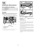
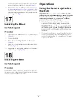


Figure 34
1.
Hydraulic supply hose (45°
fitting—extend)
4.
Back of the machine
2.
Hydraulic control manifold
5.
Hydraulic supply hose
(straight fitting—retract)
3.
45° hydraulic fitting (port
B—extend)
6.
90° hydraulic fitting (port
A—retract)
4.
Install the 45° fitting of the hydraulic supply hose to
the 90° hydraulic fitting in port B (retract) of the lift
cylinder control valve (
5.
Route the hose along the other hose (
) that
you routed in step
.
6.
Install the straight fitting of the hydraulic supply hose
to the 90° hydraulic fitting in port A of the hydraulic
control manifold (
).
7.
Secure the hoses to the chassis with cable ties as
required to support the hoses and prevent interference
with moving parts of the machine.
10
Connecting the Lift Cylinder
Hoses to the Manifold
No Parts Required
Procedure
1.
Connect the lift cylinder hose with the male
quick-disconnect coupling with the female
quick-disconnect coupling at port C4 of the manifold
(
).
Figure 35
1.
Female quick-disconnect
coupling (manifold port
C4)
4.
Male quick-disconnect
coupling (manifold port
C3)
2.
Male quick-disconnect
coupling (lift cylinder hose)
5.
Female quick-disconnect
coupling (lift cylinder hose)
3.
Manifold
2.
Connect the lift cylinder hose with the female
quick-disconnect coupling with the male
quick-disconnect coupling at port C3 of the manifold
(
).
3.
Replenish the transaxle reservoir (non-HDX-Auto
Workman models) or the hydraulic reservoir
(HDX-Auto Workman models) with the specified fluid;
refer to the
Operator’s Manual
for your machine.
4.
Ensure that all of the hydraulic fittings are tight and
check for leaks.
16